Download
1 / 24
260 likes | 592 Views
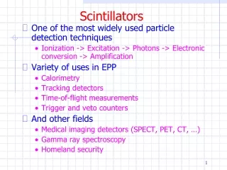
Scintillators. Scintillators. When radiation interacts with certain types of materials, it produces flashes of light (scintillation) Materials that respond this way are called scintillators. These flashes can be collected and counted to obtain a measure of the radiation intensity.

E N D
Scintillators When radiation interacts with certain types of materials, it produces flashes of light (scintillation) Materials that respond this way are called scintillators. These flashes can be collected and counted to obtain a measure of the radiation intensity. Amount of flashes produced is proportional to the energy deposited in the crystal
Early detectors 1903 – Crookes invented a device called a spinthariscope used to see scintillations from alpha particle using zinc sulfide detector 1908- Regener used diamonds to count the scintillations of alpha particles 1944- Photomultiplier tube was invented
Characteristics High efficiency Efficiency should be linear over a wide energy range Transparent Should be easily made Index of refraction should be close to glass No material fits all of these criteria
F vs P Flourensence- emission of visible radiation from a material. Prompt and delayed Phosphoresence- emission of a longer wavelength light but at a much slower time interval Good scintillator should convert most of the energy to prompt flouresence
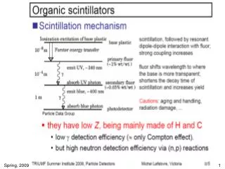
Scintillators • Organic Anthracine, Napthaline, Stilbene • Fast response but low efficiency • Beta and neutron detection • Can be solid or liquid • Inorganic NaI, CsI, ZnS, HgI, BGO • Slower response but higher efficiency • Higher density for gamma detection • Usually solid
Organic • Pure crystals • Anthracine highest efficiency of any organic • Stilbene pulse shape discrimination • Fragile • Hard to get in large sizes
Plastic Scintillators Organic scintillators are dissolved in a solvent and can be polymerized Can easily be made in large volumes Inexpensive Have to worry about self absorption
Liquid • Efficient for low energy beta particles and x rays • Can be in large volumes • High efficiencies • More Later on Liquid Scintilation process • Toxic Benzene, Toluene, Xylene • Non-toxic POP, POPOP, Ultima Gold
Other Organic scintillators • Thin Film • Can be used as transmission detectors • Loaded Organic detectors • Can add high Z material to increase efficiency of energy conversion to light but lowers light transmission through material • Can add high neutron capture cross section material so can detect Neutrons through the proton recoil reaction
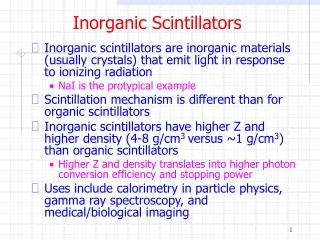
Inorganic Valence band- bound electrons Conduction band- electrons that can travel within the crystal Forbidden band- where electrons can not go Electrons jump from valence band to conduction band Probability of conduction band e- returning to the valence band is small, so we add activators to the crystal
Band gap Band gap is the energy difference between the valence band and the conduction band In conductors the band gap is 0 In insulators the band gap is larger In semi-conductors the band gap is small
Activators Are impurities that are added to the crystal to improve the probability of the e-returning to the valence band and hence releasing light in a wavelength we can detect Impurities create energy states that in the forbidden zone of the original crystal giving the e- jumping off points
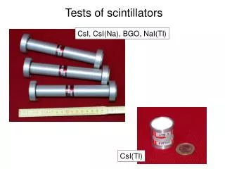
Inorganics • Sodium iodide crystals doped with thallium (NaI(Tl)) • Most common scintillator • generally employed for gamma and x-ray detection • Can be made large • Has excellent light production • Very hydroscopic • Linear response • Very fragile
Inorganics • Cesium Iodide (CsI) with Tl or Na • Less fragile than NaI • Can be shaped • Denser material • Pulse shape discrimination properties can differentiate between different type of radiation • Good if need small efficient detector
Inorganics • Zinc sulfide doped with silver (ZnS(Ag)) , • well suited for alpha and heavy ion detection • Efficiency similar to NaI(Tl) • Polycrystaline form limits size • they use a large area but thin crystals for portable survey instruments • First type of radiation detector
Scintillators • Bismuth Germanate (BGO) • Pure scintillator • High density • Not as fragile as NaI • High efficiency • Poor energy resolution • LaBr3(Ce)- Lanthanum Bromide • High density • Good resolution • Others • BaF2 • CaF2 • CsF
Scintillator crystal • Must be clear with no defects • What would the effect on light propagation if the crystal had a • Crack • Cloudiness • Other than doped impurities
Photomultiplier Tube Device that changes a small number of photons created in a scintillator (or other process) into a number of electrons that can easily be counted. Glass enclosed, vacuum sealed components Shock and vibration sensitive Magnetic fields will effect PTMs
Photomultiplier Tube (PMT) • Photocathode- has the unique characteristic of producing electrons when photons strikes its surface (photoelectric effect) • Dynodes- When each electron from the photocathode hits the first dynode, several electrons are produced (multiplication), this sequence continues until the electron pulse is now millions of times larger then it was at the beginning of the tube
Photomultiplier Tube (PMT) cont • Anode- At this point the millions of electrons are collected by an anode at the end of the tube forming an electronic pulse. • Signal – multiplied pulse sent to other electronics for processing • Signal collected at the anode has been multiplied many times from when it entered the photocathode
Photomultiplier Tube (PMT) Incident Ionizing Radiation Photomultiplier Tube Pulse Measuring Device Light Photon - Sodium-Iodide Crystal Dynode Anode Photocathode Optical Window
PMT Several configurations Venetian blind Box and grid Linear structure Circular grid
Types Venetian blind- old , slow response time, not used much Box and grid- old and slow but is good for large PMT Circular grid and linear structure-faster response time