Download
1 / 24
240 likes | 372 Views
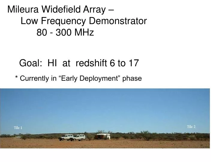
Mileura Widefield Array – Low Frequency Demonstrator 80 - 300 MHz. Goal: HI at redshift 6 to 17. * Currently in “Early Deployment” phase. Tile 1. 500 Tiles. Layout in field instantaneous UV coverage. Ultimately…. 500 Tiles…. 1 km. Distance [km].

E N D
Mileura Widefield Array – Low Frequency Demonstrator 80 - 300 MHz Goal: HI at redshift 6 to 17 * Currently in “Early Deployment” phase
500 Tiles Layout in field instantaneous UV coverage Ultimately…. 500 Tiles… 1 km Distance [km]
Current Signal Path (Early Deployment) 16 dual-pol dipoles “Tile” Beamformer … for each tile… IF Converter 80-350 MHz 200m coax A/D 16Msampl/sec Linux box+VSIB +TByte RAID +software processing LVDS 26-30 MHz Tile 2 Tile 3
Current Signal Path (Early Deployment) 16 dual-pol dipoles “Tile” Beamformer … for each tile… IF Converter 80-350 MHz 200m coax A/D 16Msampl/sec Linux box+VSIB +TByte RAID +software processing LVDS 26-30 MHz Tile 2 Tile 3
Current Signal Path (Early Deployment) 16 dual-pol dipoles “Tile” Beamformer … for each tile… IF Converter 80-350 MHz 200m coax A/D 16Msampl/sec Linux box+VSIB +TByte RAID +software processing LVDS 26-30 MHz Tile 2 Tile 3
Eric’s IF Converter 0-300MHz in 10 MHz 4 MHz 26-30MHz out
Current Signal Path (Early Deployment) 16 dual-pol dipoles “Tile” Beamformer … for each tile… IF Converter 80-350 MHz 200m coax A/D 16Msampl/sec Linux box+VSIB +TByte RAID +software processing LVDS 26-30 MHz Tile 2 Tile 3
8bit digital out • Portable • Toolkit for • Radio Expts • software • suite Analog 26-30 MHzin
Current Signal Path (Early Deployment) 16 dual-pol dipoles “Tile” Beamformer … for each tile… IF Converter 80-350 MHz 200m coax A/D 16Msampl/sec Linux box+VSIB +TByte RAID +software processing LVDS 26-30 MHz Tile 2 Tile 3
Phases are well behaved for all declinations
Sample deep Spectra - 1kHz resolution 1/2 hr 1 hr Power relative to Sky [dB] 1 hr 1/2 hr
Current Signal Path (Early Deployment) 16 dual-pol dipoles “Tile” Beamformer … for each tile… IF Converter 80-350 MHz 200m coax A/D 16Msampl/sec Linux box+VSIB +TByte RAID +software processing LVDS 26-30 MHz Tile 2 Tile 3
Beamformer Beamformer Beamformer Beamformer Next Generation Signal Path Group 16 tiles into “NODE” 80-350 MHz Node Electronics 16 x 2 pol inputs Correlator < 1 km fibre
Beamformer 6bit A/D PP Filter select 32 MHz 8 KHz Channels Next Generation Signal Path Node serves 16 tiles: 80-350 MHz Node Electronics 16 x 2 pol inputs ………… Correlator < 1 km fibre