Download

1 / 29
350 likes | 701 Views
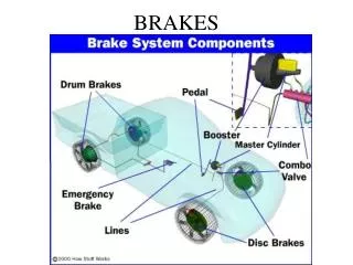
chapter 62. Power Brakes. FIGURE 62.1 Typical vacuum brake booster assembly. The vacuum hose attaches to the intake manifold of the engine. The brake pedal travel sensor is an input sensor for the antilock braking system.

E N D
chapter62 Power Brakes
FIGURE 62.1 Typical vacuum brake booster assembly. The vacuum hose attaches to the intake manifold of the engine. The brake pedal travel sensor is an input sensor for the antilock braking system.
FIGURE 62.2 A wide brake pedal allows two-foot braking if power assist is lost.
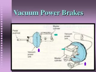
FIGURE 62.6 Vacuum brake boosters operate on the principle of pressure differential.
FIGURE 62.7 The charcoal filter traps gasoline vapors that are present in the intake manifold and prevents them from getting into the vacuum chamber of the booster.
FIGURE 62.8 (a) Many vacuum brake booster check valves are located where the vacuum hose from the engine (vacuum source) attaches to the vacuum booster. (b) This one-way valve prevents the loss of vacuum when the engine is off. The diaphragm inside allows air to flow in one direction only.
FIGURE 62.9 Not all check valves are located at the vacuum line to the booster housing connection. This vehicle uses an inline check valve located between the intake manifold of the engine and the vacuum brake booster.
FIGURE 62.10 Cross-sectional view of a typical vacuum brake booster assembly.
FIGURE 62.11 In the release position (brake pedal up), the vacuum is directed to both sides of the diaphragm.
FIGURE 62.12 Simplified diagram of a vacuum brake booster in the apply position. Notice that the atmospheric valve is open and air pressure is being applied to the diaphragm.
FIGURE 62.13 Cross section of a vacuum brake booster in the hold position with both vacuum and atmospheric valves closed. Note that the reaction force from the brake fluid pressure is transferred back to the driver as a reaction force to the brake pedal.
FIGURE 62.14 Cutaway showing a dual-diaphragm (tandem) vacuum brake booster.
FIGURE 62.15 A typical brake assist system uses a brake pedal travel sensor and a BAS solenoid to apply the brakes during a panic condition.
FIGURE 62.16 When the brake assist function operates, the brake force is much higher than normal.
FIGURE 62.17 Typical adjustable pushrod. This adjustment is critical for the proper operation of the braking system. If the pushrod is too long, the brakes may be partially applied during driving. If the rod is too short, the brake pedal may have to be depressed farther down before the brakes start to work.
FIGURE 62.18 Typical vacuum brake booster pushrod gauging tool. (a) The tool is first placed against the mounting flange of the master cylinder and the depth of the piston determined. (b) The gauge is then turned upside down and used to gauge the pushrod length. Some vacuum brake boosters do not use adjustable pushrods. If found to be the incorrect length, a replacement pushrod of the correct length should be installed.
FIGURE 62.19 A holding fixture and a long tool being used to rotate the two halves of a typical vacuum brake booster.
FIGURE 62.20 Exploded view of a typical dual-diaphragm vacuum brake booster assembly.
FIGURE 62.21 Hydro-Boost unit attaches between the bulkhead and the master cylinder and is powered by the power steering pump.
FIGURE 62.23 A Hydro-Boost hydraulic booster in the unapplied position.
FIGURE 62.24 A Hydro-Boost hydraulic booster as the brakes are applied.
FIGURE 62.25 A Hydro-Boost hydraulic booster in the holding position.
FIGURE 62.26 A typical Hydro-Boost hydraulic line arrangement showing the pump, steering gear, and brake booster assembly.
FIGURE 62.27 Pressure and flow analyzer installation to check the power steering pump output.
FIGURE 62.28 The accumulator should be able to hold pressure and feel tight when hand force is used to try to move it.