Download
1 / 15
170 likes | 291 Views
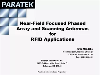
Near-Field Focused Phased Array and Scanning Antennas for RFID Applications. Greg Mendolia Vice President, Product Strategy Office: 443-259-0140 x 130 Fax: 443-259-0451. Paratek Microwave, Inc. 6935 Oakland Mills Road, Suite G Columbia, MD 21045.

E N D
Near-Field Focused Phased Array and Scanning Antennas forRFID Applications Greg Mendolia Vice President, Product Strategy Office: 443-259-0140 x 130 Fax: 443-259-0451 Paratek Microwave, Inc. 6935 Oakland Mills Road, Suite G Columbia, MD 21045 Paratek Confidential and Proprietary
Founded in 1998 to develop innovative RF components based upon the company’s proprietary materials technology, ParascanTM The Parascan™ materials science enabled the development of Paratek’s thin film, thick film and bulk material electronically tunable capacitors Electronic tunable RF components led to development of smart scanning antennas Independent, multi-beam, 360° steering Frequency coverage from 30MHz to 3 GHz Fast scanning in azimuth, elevation and frequency Re-configurable aperture for wide beam acquisition and then narrow steerable beam Maintain uninterrupted communications, increased LPI/LPD, higher capacity through frequency reuse Null steering for increased anti-jam Higher gain Horizontal and vertical polarization diversity mitigates multipath Paratek Microwave, Inc.
Accurate reading of 100% of the tags is essential RFID Technology Challenges Tags inside moving payload - - B U T - - • Technical limitations reduce tag read rates • Reader reception of tag data vulnerable to obstruction and de-tuning from metal, liquid and dense materials • Conventional reader antennas do not track and “stare” at moving tags - - I M P A C T - - • Slow industry adoption due to technology shortfalls
Near Field Focused, Scanning Phased Array (NFA) Paratek Solution • Antenna power is surgically directed at – and focused on – targeted RFID tags by increasing power levels in the near field without polluting spectrum in the far field • Antenna RF power is focused at the tag instead of spread over the entire area • More signal power delivered at the tag => more tags read and better ability to write to tags • Multipath and interference problems reduced => decreased tag contention • Antenna tracks tags as they pass by • Increased beam dwell time on tag => longer read time • Direction of tag movement can be detected • Are items entering or leaving the area? • KEY RESULT: Dramatically improved tag read rates for RFID unfriendly materials
Paratek NFA vs. Conventional Reader Antenna Tag Tag Conventional Reader Antenna Energy Distribution Paratek Near Field Focused Phased Array Antenna Lower field intensity in near field 6dBi gain limit in far field Higher field intensity in near field 6dBi gain limit in far field • Near Field Focused Phased Array amplifies and focuses RF to increase power in the near field • Arrays of elements are used to control energy focus and distribution • RF power decays quickly so that power levels in the far field are comparable to standard antennas • Compliant with FCC energy levels in far field • Permits higher near field energy intensity at the tag location
Paratek NFA vs. Conventional Phased Array Antenna Tag Tag Conventional Far Field Focused Array Antenna Paratek Near Field Focused Phased Array Antenna Lower field intensity in near field 6dBi gain limit in far field Higher field intensity in near field 6dBi gain limit in far field • Conventional arrays focus energy in the far-field, not near field • Paratek re-engineers the phase of each element in the array, focusing the energy in the near field where the tags are located • The depth and direction of the focused region can be easily steered with standard phased array electronics
Paratek NFA vs. Conventional Array Reader Antenna Paratek NFA Antenna Directivity: 0-3 meters Conventional 1x8 Far-Field Array Antenna Directivity: 0-3 meters Near Field EIRP RF energy focused on tags RF energy not where its needed
Paratek NFA vs. Conventional Array Reader Antenna Paratek NFA Antenna Directivity: 0-30 meters Conventional 1x8 Far-Field Array Antenna Directivity: 0-30 meters Far Field EIRP High far field RF energy (pollutes spectrum) Far field RF energy dispersed
Paratek NFA vs. Conventional Array 9 dB Improvement Over Conventional Antennas in Near Field / Far Field Ratio Target focus range: NFA is 4.5 dB higher NFA is 4.5dB lower
Paratek NFA vs. Conventional Array Comparative Statistical Read Rate (tags on surface of cases of bottled water) Same far-field EIRP 275% greater read rate @ 5’ 1,060% greater read rate @ 6’
Paratek Scanning Antenna 17” 9.5” 9.5 lb Pattern • Antenna Characteristics: • 862 - 928 MHz • Passive Tx/Rx, 30 dBm max • Gain 6.3 – 8.4 dBi • Dual linear polarization V/H • 27 dB isolation V-H ports • Full 360° azimuth scan range • 50° Azimuth beam (-3dB) • 70° Elevation beam (-3dB) • < -10 dB Side/back lobe • > 12 dB Return loss, 50 ohm • < 1 ms Beam switch/scan
8dBi 10dB Paratek Scanning Antenna RFID Vertical Beam Elevation Plane Azimuth Plane
Video 1 Conventional Far Field Focused Array Antenna
Video 2 Paratek Near Field Focused Phased Array Antenna
Summary • Paratek’s Near Field Focused, Scanning Phased Array (NFA) antenna dramatically improves tag read rates under all conditions, especially RFID unfriendly materials, while also enhancing the ability to write to tags • Electronic steering enables tracking of tags for increased acquisition time => Results in dramatically improved read rates, as well as identification of direction of travel for tagged products • Directed and controlled RF energy reduces tag contention and multipath issues • NFA transmitted RF energy (EIRP) decays at a faster rate over distance => Results in lower far field interference to other products or to other RFID systems