Download
1 / 18
200 likes | 691 Views
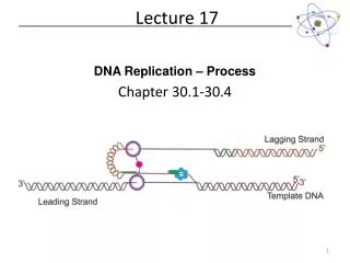
Lecture 17. OUTLINE The MOS Capacitor (cont’d) Small-signal capacitance (C-V characteristics) Reading : Pierret 16.4; Hu 5.6. v ac. MOS Capacitance Measurement. V G is scanned slowly Capacitive current due to v ac is measured. C-V Meter. MOS Capacitor. i ac. GATE.

E N D
Lecture 17 OUTLINE • The MOS Capacitor (cont’d) • Small-signal capacitance (C-V characteristics) Reading: Pierret 16.4; Hu 5.6
vac MOS Capacitance Measurement • VG is scanned slowly • Capacitive current due • to vac is measured C-V Meter MOS Capacitor iac GATE Semiconductor EE130/230A Fall 2013 Lecture 17, Slide 2
MOS C-V Characteristics (p-type Si) accumulation depletion inversion VG VFB VT Qinv C slope = -Cox Cox Ideal C-V curve: VG VFB VT accumulation depletion inversion EE130/230A Fall 2013 Lecture 17, Slide 3
Capacitance in Accumulation (p-type Si) • As the gate voltage is varied, incremental charge is added (or subtracted) to (or from) the gate and substrate. • The incremental charges are separated by the gate oxide. M O S DQ Q -Q -DQ Cox EE130/230A Fall 2013 Lecture 17, Slide 4
Flat-Band Capacitance(p-type Si) • At the flat-band condition, variations in VG give rise to the addition/subtraction of incremental charge in the substrate, at a depth LD • LD is the “extrinsic Debye Length,” a characteristic screening distance, or the distance where the electric field emanating from a perturbing charge falls off by a factor of 1/e Cox CDebye EE130/230A Fall 2013 Lecture 17, Slide 5
Capacitance in Depletion (p-type Si) • As the gate voltage is varied, the depletion width varies. • Incremental charge is effectively added/subtracted at a depth W in the substrate. M O S DQ Q W -DQ -Q Cox Cdep EE130/230A Fall 2013 Lecture 17, Slide 6
Capacitance in Inversion (p-type Si) • CASE 1: Inversion-layer charge can be supplied/removed quickly enough to respond to changes in gate voltage. • Incremental charge is effectively added/subtracted at the surface of the substrate. DQ Time required to build inversion-layer charge = 2NAto/ni, where to = minority-carrier lifetime at surface M O S WT -DQ Cox EE130/230A Fall 2013 Lecture 17, Slide 7
Capacitance in Inversion (p-type Si) • CASE 2: Inversion-layer charge cannot be supplied/removed quickly enough to respond to changes in gate voltage. • Incremental charge is effectively added/subtracted at a • depth WT in the substrate. DQ M O S WT -DQ Cox Cdep EE130/230A Fall 2013 Lecture 17, Slide 8
Supply of Substrate Charge (p-type Si) Accumulation: Depletion: Inversion: Case 1 Case 2 C. C. Hu, Modern Semiconductor Devices for ICs, Figure 5-17 EE130/230A Fall 2013 Lecture 17, Slide 9
MOS Capacitor vs. MOS Transistor C-V(p-type Si) C MOS transistor at any f, MOS capacitor at low f, or quasi-static C-V Cmax=Cox CFB MOS capacitor at high f Cmin VG accumulation depletion inversion VFB VT EE130/230A Fall 2013 Lecture 17, Slide 10
Quasi-Static C-V Measurement(p-type Si) C Cmax=Cox CFB Cmin VG accumulation depletion inversion VFB VT The quasi-static C-V characteristic is obtained by slowly ramping the gate voltage (< 0.1V/s), while measuring the gate current IG with a very sensitive DC ammeter. C is calculated from IG = C·(dVG/dt) EE130/230A Fall 2013 Lecture 17, Slide 11
C Cox Cmin VG VT VFB Deep Depletion(p-type Si) • If VG is scanned quickly, Qinv cannot respond to the change in VG. Then the increase in substrate charge density Qs must come from an increase in depletion charge density Qdep • depletion depth W increases as VG increases • C decreases as VG increases EE130/230A Fall 2013 Lecture 17, Slide 12
MOS C-V Characteristic for n-type Si C MOS transistor at any f, MOS capacitor at low f, or quasi-static C-V Cmax=Cox CFB MOS capacitor at high f Cmin VG inversion depletion accumulation VT VFB EE130/230A Fall 2013 Lecture 17, Slide 13
C QS Cox HF-Capacitor VG VT VFB Examples: C-V Characteristics • Does the QS or the HF-capacitor C-V characteristic apply? • MOS capacitor, f=10kHz • MOS transistor, f=1MHz • MOS capacitor, slow VG ramp • MOS transistor, slow VG ramp EE130/230A Fall 2013 Lecture 17, Slide 14
Example: Effect of Doping • How would the normalized C-V characteristic below change if the substrate doping NA were increased? • VFB • VT • Cmin C/Cox 1 VT VFB EE130/230A Fall 2013 Lecture 17, Slide 15
Example: Effect of Oxide Thickness • How would the normalized C-V characteristic below change if the oxide thickness xo were decreased? • VFB • VT • Cmin C/Cox 1 VT VFB EE130/230A Fall 2013 Lecture 17, Slide 16
Derivation of Time to Build Inversion-Layer Charge(for an NMOS device, i.e. p-type Si) The net rate of carrier generation is: (ref. Lecture 5, Slide 24) where since trap states that contribute most significantly to G-R have an associated energy level near the middle of the band gap. Within the depletion region, n and p are negligible, so where tn tp to Therefore, the rate at which the inversion-layer charge density Qinv (units: C/cm2) increases due to thermal generation within the depletion region (of width W) is EE130/230A Fall 2013 Lecture 17, Slide 17
For a fixed value of gate voltage, the total charge in the semiconductor is fixed: Therefore The solution to this differential equation is where EE130/230A Fall 2013 Lecture 17, Slide 18