Download
1 / 34
360 likes | 594 Views
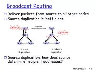
Broadcast and multicast routing. duplicate creation/transmission. duplicate. duplicate. in-network duplication. source duplication. R1. R2. R3. R4. R1. R2. R3. R4. Broadcast Routing. Deliver packets from srce to all other nodes Source duplication is inefficient:.

E N D
duplicate creation/transmission duplicate duplicate in-network duplication sourceduplication R1 R2 R3 R4 R1 R2 R3 R4 Broadcast Routing • Deliver packets from srce to all other nodes • Source duplication is inefficient: • Source duplication: how does source determine recipient addresses
In-network duplication • Flooding: when node receives brdcst pckt, sends copy to all neighbors • Problems: cycles & broadcast storm • Controlled flooding: node only brdcsts pkt if it hasn’t brdcst same packet before • Node keeps track of pckt ids already brdcsted • Or reverse path forwarding (RPF): only forward pckt if it arrived on shortest path between node and source • Spanning tree • No redundant packets received by any node
(b) Broadcast initiated at D (a) Broadcast initiated at A A A D D G G B E E B F F c c Spanning Tree • First construct a spanning tree • Nodes forward copies only along spanning tree
3 A A D G D G E E B B F F c c 4 2 5 1 • Stepwise construction of spanning tree (b) Constructed spanning tree Spanning Tree: Creation • Center node • Each node sends unicast join message to center node • Message forwarded until it arrives at a node already belonging to spanning tree
Source-based trees Shared tree Multicast Routing: Problem Statement • Goal: find a tree (or trees) connecting routers having local mcast group members • tree: not all paths between routers used • source-based: different tree from each sender to rcvrs • shared-tree: same tree used by all group members
Approaches for building mcast trees Approaches: • source-based tree: one tree per source • shortest path trees • reverse path forwarding • group-shared tree: group uses one tree • minimal spanning (Steiner) • center-based trees …we first look at basic approaches, then specific protocols adopting these approaches
1 i 5 4 3 6 2 Shortest Path Tree • mcast forwarding tree: tree of shortest path routes from source to all receivers • Dijkstra’s algorithm S: source LEGEND R1 R4 router with attached group member R2 router with no attached group member R5 link used for forwarding, i indicates order link added by algorithm R3 R7 R6
Reverse Path Forwarding if (mcast datagram received on incoming link on shortest path back to center) then flood datagram onto all outgoing links else ignore datagram • rely on router’s knowledge of unicast shortest path from it to sender • each router has simple forwarding behavior:
Reverse Path Forwarding: example S: source LEGEND R1 R4 router with attached group member R2 router with no attached group member R5 datagram will be forwarded R3 R7 R6 datagram will not be forwarded • result is a source-specific reverse SPT • may be a bad choice with asymmetric links
Reverse Path Forwarding: pruning • forwarding tree contains subtrees with no mcast group members • no need to forward datagrams down subtree • “prune” msgs sent upstream by router with no downstream group members LEGEND S: source R1 router with attached group member R4 router with no attached group member R2 P P R5 prune message links with multicast forwarding P R3 R7 R6
Shared-Tree: Steiner Tree • Steiner Tree: minimum cost tree connecting all routers with attached group members • problem is NP-complete • excellent heuristics exists • not used in practice: • computational complexity • information about entire network needed • monolithic: rerun whenever a router needs to join/leave
Center-based trees • single delivery tree shared by all • one router identified as “center” of tree • to join: • edge router sends unicast join-msg addressed to center router • join-msg “processed” by intermediate routers and forwarded towards center • join-msg either hits existing tree branch for this center, or arrives at center • path taken by join-msg becomes new branch of tree for this router
Center-based trees: an example Suppose R6 chosen as center: LEGEND R1 router with attached group member R4 3 router with no attached group member R2 2 1 R5 path order in which join messages generated R3 1 R7 R6
Internet Multicasting Routing: DVMRP • DVMRP: distance vector multicast routing protocol, RFC1075 • flood and prune: reverse path forwarding, source-based tree • RPF tree based on DVMRP’s own routing tables constructed by communicating DVMRP routers • no assumptions about underlying unicast • initial datagram to mcast group flooded everywhere via RPF • routers not wanting group: send upstream prune msgs
DVMRP: continued… • soft state: DVMRP router periodically (1 min.) “forgets” branches are pruned: • mcast data again flows down unpruned branch • downstream router: reprune or else continue to receive data • routers can quickly regraft to tree • following IGMP join at leaf • odds and ends • commonly implemented in commercial routers • Mbone routing done using DVMRP
Tunneling Q: How to connect “islands” of multicast routers in a “sea” of unicast routers? logical topology physical topology • mcast datagram encapsulated inside “normal” (non-multicast-addressed) datagram • normal IP datagram sent thru “tunnel” via regular IP unicast to receiving mcast router • receiving mcast router unencapsulates to get mcast datagram
not dependent on any specific underlying unicast routing algorithm (works with all) two different multicast distribution scenarios : PIM: Protocol Independent Multicast • Dense: • group members densely packed, in “close” proximity. • bandwidth more plentiful • Sparse: • # networks with group members small wrt # interconnected networks • group members “widely dispersed” • bandwidth not plentiful
Dense group membership by routers assumed until routers explicitly prune data-driven construction on mcast tree (e.g., RPF) bandwidth and non-group-router processing profligate Sparse: no membership until routers explicitly join receiver- driven construction of mcast tree (e.g., center-based) bandwidth and non-group-router processing conservative Consequences of Sparse-Dense Dichotomy:
PIM- Dense Mode • flood-and-prune RPF, similar to DVMRP but • underlying unicast protocol provides RPF info for incoming datagram • less complicated (less efficient) downstream flood than DVMRP reduces reliance on underlying routing algorithm • has protocol mechanism for router to detect it is a leaf-node router
center-based approach router sends join msg to rendezvous point (RP) intermediate routers update state and forward join after joining via RP, router can switch to source-specific tree increased performance: less concentration, shorter paths R1 R4 join R2 join R5 join R3 R7 R6 all data multicast from rendezvous point rendezvous point PIM - Sparse Mode
sender(s): unicast data to RP, which distributes down RP-rooted tree RP can extend mcast tree upstream to source RP can send stop msg if no attached receivers “no one is listening!” R1 R4 join R2 join R5 join R3 R7 R6 all data multicast from rendezvous point rendezvous point PIM - Sparse Mode
PIM-SM(1) S Source A B RP D C E R2 R1 Receiver 1 Receiver 2
PIM-SM(2) S Receiver 1 Joins Group GC Creates (*, G) State, Sends(*, G) Join to the RP Source A B RP D Join C E R2 R1 Receiver 1 Receiver 2
PIM-SM(3) S RP Creates (*, G) State Source A B RP D C E R2 R1 Receiver 1 Receiver 2
PIM-SM(4) S Source Sends DataA Sends Registration to the RP Source IP tunnel between A and RP since multicast tree is not established Register Data A B RP D C E R2 R1 Receiver 1 Receiver 2
PIM-SM(5) S RP decapsulates RegistrationForwards Data Down the Shared TreeSends Joins Towards the Source Source join join A B RP D C E R2 R1 Receiver 1 Receiver 2
PIM-SM(6) S RP Sends Register-Stop OnceData Arrives Natively Source Register-Stop A B RP D C E R2 R1 Receiver 1 Receiver 2
PIM-SM(7)SPTSwitchover S C Sends (S, G) Joins to Join theShortest Path Tree (SPT) Source A B RP D join C E R2 R1 Receiver 1 Receiver 2
PIM-SM(8) S C starts receiving Data natively Source A B RP D C E R2 R1 Receiver 1 Receiver 2
PIM-SM(9) S C Sends Prunes Up the RP tree forthe Source. RP Deletes (S, G) OIF andSends Prune Towards the Source Source Prune Prune A B RP D Prune C E R2 R1 Receiver 1 Receiver 2
PIM-SM(10) S B, RP pruned Source A B RP D C E R2 R1 Receiver 1 Receiver 2
PIM-SM(11) S New receiver2 joinsE Creates State and Sends (*, G) Join Source A B RP D C E join R2 R1 Receiver 1 Receiver 2
PIM-SM(12) S C Adds Link Towards E to the OIFList of Both (*, G) and (S, G)Data from Source Arrives at E Source A B RP D C E R2 R1 Receiver 1 Receiver 2