Download
1 / 31
310 likes | 421 Views
Lecture 17 I/O Interfaces and I/O Busses. Storage System Issues. Historical Context of Storage I/O Storage I/O Performance Measures Secondary and Tertiary Storage Devices Processor Interface Issues I/O Buses Redundant Arrays of Inexpensive Disks (RAID). Disk Time Example.

E N D
Lecture 17 I/O Interfaces and I/O Busses CS510 Computer Architectures
Storage System Issues • Historical Context of Storage I/O • Storage I/O Performance Measures • Secondary and Tertiary Storage Devices • Processor Interface Issues • I/O Buses • Redundant Arrays of Inexpensive Disks (RAID) CS510 Computer Architectures
Disk Time Example • Disk Parameters: • Transfer size is 8K bytes • Advertised average seek is 12 ms • Disk spins at 7200 RPM • Transfer rate is 4 MB/sec • Controller overhead is 2 ms • Assume that disk is idle so no queuing delay • What is Average Disk Access Time for a Sector? • Ave seek + ave rot delay + transfer time + controller overhead • 12 ms + 0.5/(7200 RPM/60) + 8 KB/4 MB/s + 2 ms • 12 + 4.15 + 2 + 2 = 20 ms • Advertised seek time assumes no locality: typically 1/4 to 1/3 advertised seek time • Average Disk Access Time for a Sector: 20 ms => 12 ms CS510 Computer Architectures
Processor Interface Issues • Interconnections • Busses • Processor interface • Interrupts • Memory mapped I/O • I/O Control Structures • Polling • Interrupts • DMA • I/O Controllers • I/O Processors • Capacity, Access Time, Bandwidth CS510 Computer Architectures
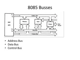
CPU Memory memory bus Interface Interface Peripheral Peripheral CPU 40 Mbytes/sec optimistically 10 MIPS processor completely saturates the bus! VME bus Multibus-II Nubus Memory Interface Interface Peripheral Peripheral I/O Interface Independent I/O Bus Seperate I/O instructions (in,out) Lines distinguish between I/O and memory transfers Common Memory & I/O bus CS510 Computer Architectures
CPU Single Memory & I/O Bus No Separate I/O Instructions ROM Memory Interface Interface RAM Peripheral Peripheral CPU I/O $ L2 $ Memory Bus I/O bus Memory Bus Adapter Memory Mapped I/O CS510 Computer Architectures
Is data ready? CPU no yes read data Memory IOC store data device done? no yes Programmed I/O (Polling) • busy on wait loop • not an efficient way to • use the CPU, unless • the device is very fast! • but checks for I/O • completion can be • dispersed among • computationally • intensive code CS510 Computer Architectures
CPU add sub and or nop (1) I/O interrupt user program (2) save PC Memory IOC (3) interrupt service addr device read store ... rti interrupt service routine (4) memory 1000 transfers/second: 1000 interrupts @ 2 msec per interrupt=> 2 msec 1000 interrupt service @ 98 msec each=> 98 msec 100 msec = 0.1 CPU seconds Interrupt Driven Data Transfer User program halts only during actual transfer CS510 Computer Architectures
Time to do 1000 xfers in 1 msec: 1 DMA set-up sequence: @ 50 msec 1 interrupt: @ 2 msec 1 interrupt service sequence: @ 48 msec 100msec .0001 second of CPU time CPU sends a starting address, direction(R/W), and word count to DMAC. Then issues "start". CPU 0 ROM Memory DMAC IOC Memory Mapped I/O RAM I/O device DMAC provides; Peripheral controller Handshake signals Memory Addresses Handshake signals Peripherals DMAC n Direct Memory Access CS510 Computer Architectures
D1 CPU issues instruction to IOP IOP (1) D2 interrupts when done main memory bus (4) Mem . . . target device Dn I/O bus where cmnds are CPU IOP OP Device Address looks in memory for commands (2) Command (3) memory OP Addr Cnt Other what to do special requests where to put data how much Input/Output Processors Device to/from memory transfers are controlled by the IOP directly. IOP steals memory cycles from CPU CS510 Computer Architectures
Relationship to Processor Architecture • I/O instructions and busses have largely disappeared • Interrupt vectors have been replaced by jump tablesPC <- M [ IVA + interrupt number ] • Interrupts: • Stack replaced by shadow registers • Handler saves registers and re-enables higher priority interrupts CS510 Computer Architectures
Relationship to Processor Architecture • Caches required for processor performance cause problems for I/O • Flushing is expensive, I/O pollutes cache • Solution is borrowed from shared memory multiprocessors "snooping" • Virtual memory frustrates DMA • Stateful processors are hard to switch context CS510 Computer Architectures
Network Channel Backplane >1000 m 10 - 100 m Distance 1 m 10 - 100 Mb/s 40 - 1000 Mb/s Bandwidth 320 - 1000+ Mb/s high (>ms) medium Latency low (<µs) low medium Reliability high Extensive CRC Byte Parity Byte Parity Interconnect Trends • Interconnect = glue that interfaces computer system components • High speed hardware interfaces + logical protocols • Networks, channels, backplanes • Message-based • Narrow pathways • Distributed arbitration • Memory-mapped • Wide pathways • Centralized arbit. CS510 Computer Architectures
Metric VME Futur eBus MultiBus II SCSI-I Bus Width (signals) 128 96 96 25 Address data multiplexed? No Y es Y es na Data Width 16 - 32 32 32 8 Xfer Size Single/Multiple Single/Multiple Single/Multiple Single/Multiple # of Bus Masters Multiple Multiple Multiple Multiple Split Transactions No Optional Optional Optional Clocking Async Sync Async Either or d (0 ns mem) Bandwidth, Single W 25 20 37 5, 1.5 Bandwidth, Single Word (150ns mem) 12.9 10 15.5 5, 1.5 Bandwidth Multiple W 27.9 40 or d (0 ns mem) 95.2 5, 1.5 or d (150 ns mem) Bandwidth Multiple W 13.6 13.3 20.8 5, 1.5 Max # of devices 21 21 20 7 Max Bus Length .5 m .5 m .5 m 25 m Standard IEEE 1014 IEEE 896 ANSI/IEEE 1296 ANSI X3.131 Backplane Architectures Distinctions begin to blur: SCSI channel is like a bus FutureBus is like a channel (disconnect/reconnect) HIPPI forms links in high speed switching fabrics CS510 Computer Architectures
Bus-Based Interconnect • Bus: a shared communication link between subsystems • Low cost: a single set of wires is shared multiple ways • Versatility: Easy to add new devices & peripherals may even be ported between computers using common bus • Disadvantage • A communication bottleneck, possibly limiting the maximum I/O throughput • Bus speed is limited by physical factors • the bus length • the number of devices (and, hence, bus loading). • these physical limits prevent arbitrary bus speedup. CS510 Computer Architectures
Bus-Based Interconnect • Two generic types of busses: • I/O busses (sometimes called a channel) • lengthy • many types of devices connected • wide range in the data bandwidth • follow a bus standard • CPU-Memory buses (sometimes called a backplane) • short • high speed, matched to the memory system to maximize memory-CPU bandwidth • To lower costs, low cost (older) systems combine together • Bus transaction • Sending address & receiving or sending data CS510 Computer Architectures
Master Slave ° ° ° Control Lines Address Lines Data Lines Bus Protocols • Bus Master: has ability to control the bus, initiates a transaction • Bus Slave: module activated by the transaction • Bus Communication Protocol: specification of sequence of events and timing requirements in transferring information. • Asynchronous Bus Transfers: control lines (req., ack.) serve to orchestrate sequencing • Synchronous Bus Transfers: sequence relative to the common clock Multibus: 20 address, 16 data, 5 control, 50ns Pause CS510 Computer Architectures
Read transaction Clock Address Data Read Wait begin read Read complete Pipelined/Split transaction Bus Protocol Address Data Wait addr 1 addr 2 addr 3 data 0 data 1 wait 1 OK 1 Synchronous Bus Protocols CS510 Computer Architectures
Address Data Read Req. Ack. Next Address Master Asserts Address Master Asserts Data 4 Cycle Handshake t0 t1 t2 t3 t4 t5 t0:Master has obtained control and asserts address, direction, data; Waits a specified amount of time for slaves to decode target t1: Master asserts request line t2:Slave asserts ack, indicating data received t3:Master releases req t4:Slave releases ack Asynchronous Handshake Write Transaction CS510 Computer Architectures
Master Asserts Address Address Data Read Req Ack Next Address 4 Cycle Handshake t0 t1 t2 t3 t4 t5 t0:Master has obtained control and asserts address, direction; Waits a specified amount of time for slaves to decode t1:Master asserts request line t3:Master releases req, data received t4:Slave releases ack Asynchronous Handshake Read Transaction t2:Slave asserts ack, indicating ready to transmit data; Slave asserts data Time Multiplexed Bus: address and data share lines CS510 Computer Architectures
Bus Arbiter BR: Bus Request BG: Bus Grant BR BG BR BG BR BG Bus sequence: BR BG Busy data M M M BGi BGo BG BR BGi BGo BGiBGo M M M A.U. BR BR BR M M M A.U. BR A BR A BR A BR A Bus Arbitration Parallel (Centralized) Arbitration Serial Arbitration (daisy chaining) Polling CS510 Computer Architectures
Option High performance Low cost Bus Options Bus width Separate address Multiplex address & data lines & data lines Data width Wider is faster Narrower is cheaper (e.g., 32 bits) (e.g., 8 bits) Transfer size Multiple words has Single-word transfer less bus overhead is simpler Bus masters Multiple Single master (requires arbitration) (no arbitration) Split Yes - separate No - continuous transaction? Request and Reply connection is cheaper packets gets higher and has lower latency bandwidth (needs multiple masters) Clocking Synchronous Asynchronous CS510 Computer Architectures
VME FutureBus Multibus II IPI SCSI 1990 Bus Survey Signals 128 96 96 16 8 Addr/Data mux no yes yes n/a n/a Data width 16 - 32 32 32 16 8 Masters multi multi multi single multi Clocking Async Async Sync Async either MB/s 25 37 20 25 1.5 (asyn) (0ns, word) 5 (sync) 150ns word 12.9 15.5 10 = = 0ns block 27.9 95.2 40 = = 150ns block 13.6 20.8 13.3 = = Max devices 21 20 21 8 7 Max meters 0.5 0.5 0.5 50 25 Standard IEEE 1014 IEEE 896.1 ANSI/IEEE ANSI X3.129 ANSI X3.131 1296 CS510 Computer Architectures
VME • 3 96-pin connectors • 128 defined as standard, rest customer defined • 32 address • 32 data • 64 command & power/ground lines CS510 Computer Architectures
SCSI: Small Computer System Interface • Up to 8 devices to communicate on a bus or “string” at sustained speeds of 4-5 MBytes/sec • SCSI-2 up to 20 MB/sec • Devices can be slave (“target”) or master(“initiator”) • SCSI protocol: a series of phases, during which specific actions are taken by the controller and the SCSI disks • Bus Free: No device is currently accessing the bus • Arbitration: When the SCSI bus goes free, multiple devices may request (arbitrate for) the bus; fixed priority by address • Selection: informs the target that it will participate (Reselection if disconnected) • Command: the initiator reads the SCSI command bytes from host memory and sends them to the target • Data Transfer: data in or out, initiator: target • Message Phase: message in or out, initiator: target (identify, save/restore data pointer, disconnect, command complete) • Status Phase: target, just before command complete CS510 Computer Architectures
Command Setup Arbitration Selection Message Out (Identify) Command Disconnect to seek/¼ ll buf fer Message In (Disconnect) - - Bus Free - - Arbitration If no disconnect is needed Reselection Message In (Identify) Data T ransfer Data In Completion ll buf fer Disconnect to ¼ Command Completion Message In (Save Data Ptr) Status Message In (Disconnect) Message In (Command Complete) - - Bus Free - - Arbitration Reselection Message In (Identify) Message In (Restore Data Ptr) SCSI “Bus”: Channel Architecture peer-to-peer protocols initiator/target linear byte streams disconnect/reconnect CS510 Computer Architectures
Bus SBus TurboChannel MicroChannel PCI 1993 I/O Bus Survey Originator Sun DEC IBM Intel Clock Rate (MHz) 16-25 12.5-25 async 33 Addressing Virtual Physical Physical Physical Data Sizes (bits) 8,16,32 8,16,24,32 8,16,24,32,64 8,16,24,32,64 Master Multi Single Multi Multi Arbitration Central Central Central Central 32 bit read (MB/s) 33 25 20 33 Peak (MB/s) 89 84 75 111 (222) Max Power (W) 16 26 13 25 CS510 Computer Architectures
Bus Summit Challenge XDBus 1993 MP Server Memory Bus Survey Originator HP SGI Sun Clock Rate (MHz) 60 48 66 Split transaction?YesYesYes? Address lines 48 40 ?? Data lines 128 256 144 (parity) Data Sizes (bits) 512 1024 512 Clocks/transfer 4 5 4? Peak (MB/s)96012001056 Master Multi Multi Multi Arbitration Central Central Central Addressing Physical Physical Physical Slots 16 9 10 Busses/system 1 1 2 Length 13 inches 12? inches 17 inches CS510 Computer Architectures
Network Controller Processor Memory List of request blocks Node Control . . . Processor Reg. I/F Data to be transmitted DMA List of free blocks Request . . . Block Net Memory I/F List of receive blocks Receive . . . Block DMA Data received Media Peripheral Backplane Bus Communications Networks Performance limiter is memory system, OS overhead, not protocols • Send/receive queues in processor memories • Network controller copies back and forth via DMA • No host intervention needed • Interrupt host when message sent or received CS510 Computer Architectures
Peripheral Bus (VME, FutureBus, etc.) Peripheral Bus Interface/DMA Host Memory Buf fer Memory Processor µProc Cache ROM Host I/O Channel Interface Processor I/O Controller I/O Controller Architecture • Request/Response block interface • Backdoor access to host memory CS510 Computer Architectures
Application Address Space Memory-to-Memory Copy Host Processor fers (>10 MByte) OS Buf DMA over Peripheral Bus Buf fers (1 M - 4 MBytes) I/O Controller HBA Xfer over Disk Channel Embedded Controller T rack Buf fers (32K - 256KBytes) Xfer over Serial Interface I/O Device Head/Disk Assembly I/O Data Flow Impediment to high performance: multiple copies, complex hierarchy CS510 Computer Architectures