Download
1 / 29
340 likes | 614 Views
Geol 542. Lecture 25. Bodies With Holes / Stress Perturbations Around Cracks. Textbook reading: p.313-318; 354-357. 2D Elastic Solutions in Polar Coordinates. We can also take the relations from the Airy stress function:.

E N D
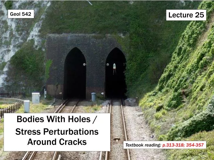
Geol 542 Lecture 25 • Bodies With Holes / • Stress Perturbations Around Cracks Textbook reading: p.313-318; 354-357
2D Elastic Solutions in Polar Coordinates We can also take the relations from the Airy stress function: and relate these to the polar coordinate system to derive general relationships (see handout):
Circular Hole in a Biaxial Stress Field If the principal stresses act along the coordinate axes, we have: sxxr = s1rsyyr = s2rsxyr = 0 The remote boundary conditions can be expressed in polar coordinates as: Note, these are simply the Mohr equations used at r = ∞, where srrsii (normal stress on a cubical element) and srqsij(i≠j). Along the hole boundary, we have local boundary conditions for a shear stress free surface: srr = srq = 0 (note, sqq ≠ 0)
Circular Hole in a Biaxial Stress Field The stress function for a circular hole is given by: where A, B, C, E, and F are constants dictated by the boundary conditions. Using the Airy equations in polar coordinates, we get: These are the general solutions for stress around a circular hole (for any loading condition).
Circular Hole in a Biaxial Stress Field Then solve for A, B, C, E, and F using the boundary conditions at r = a and r = ∞ to get: These are the specific solutions for a circular hole with biaxial loading.
Circular Hole in an Isotropic Stress Field We can use the specific solutions to solve for a circular hole for various remote boundary conditions and for any spatial location (r, q). First we consider the case of a uniform remote compression of magnitude –S (i.e., sxxr = syyr = –S; sxyr =0) and zero stress on the hole boundary (i.e., pf = 0). Substituting into the specific solution stress equations in polar coordinates, we get: So the stress intensity factor is 1+(a/r)2.
Circular Hole in an Isotropic Stress Field At the hole boundary (r = a), srr = srq = 0, andsqq = -2S everywhere (i.e., circumferential compression). So there is a stress concentration factor of 2, independent of hole size. This becomes important if 2S is greater than the uniaxial compressive strength of the rock.
Circular Hole in an Isotropic Stress Field Around the hole, principal stresses form radial and concentric stress trajectories. The mean stress (srr + sqq)/2 is constant everywhere and equal to –S. The maximum shear stress (srr –sqq)/2 is equal to S(a/r)2. So the contours (isochromatics) are concentric around the hole. Note that despite the isotropic loading, the hole perturbation creates shear stress. As r ∞, (a/r) 0, so ss(max) 0.
Circular Hole With an Internal Fluid Pressure Next, we consider the case of a uniform remote compression of magnitude –S (i.e., sxxr = syyr = –S; sxyr =0) and an internal fluid pressure acting on the hole boundary (i.e., pf = –P = –S). This condition reflects a pressurized borehole, an oil well, or magma pressure in a cylindrical conduit. Tension is positive. Substituting into the specific solution stress equations in polar coordinates, we get: The result is a homogeneous, isotropic state of stress. It’s as if the hole isn’t even there.
Circular Hole With an Internal Fluid Pressure We now consider the case of zero remote stress (i.e., sxxr = syyr = 0; sxyr =0) and an internal fluid pressure acting on the hole boundary (i.e., pf = –P). The stress components for this problem are: The result is a tension all around the hole equal in magnitude to the fluid pressure inside the hole (i.e., a stress concentration factor of -1). If this tension exceeds the tensile strength of the rock, hydrofracturingmay occur.
Spanish Peaks Dikes Muller and Pollard, 1977
Remote Stress Plus Internal Fluid Pressure We now consider the case of isotropic remote stress (i.e., sxxr = syyr = –S; sxyr =0) and an internal fluid pressure acting on the hole boundary (i.e., pf = –P), where P ≠ S. The stress components for this problem are: ≠ If P = S, this result reduces to the equations derived previously.
Biaxial Loading The specific solutions for a circular hole can also be used for the boundary conditions of biaxial loading. For example, the circumferential stress component can be solved at r = a to show: Hence, at q = 0, p: sqq = 3Sh – SH. At q = p/2, 3p/2: sqq = 3SH – Sh. (i.e., as described previously)
Circular Hole in a Biaxial Stress Field Around the hole, principal stresses are perturbed.
Stress Around Elliptical Holes A similar approach can be applied to the problem of stresses around elliptical holes. e.g., dikes, sills, veins, joints, Griffith flaws If the hole is oriented with long axes parallel to the x and y coordinate axes, respectively, the hole boundary is defined by: (x/a)2 + (y/b)2 = 1
Stress Around Elliptical Holes Just as it was more useful to use a polar coordinate system for circular holes, it is appropriate to use an elliptical curvilinear system for elliptical holes, with components x (xi) and h (eta). The transformation equations are: x = c coshxcosh y = c sinhx sin h where 2c is the focal separation (see figure).
Stress Around Elliptical Holes The stress components are: sxxshhsxh which act on any particular element in this coordinate system. It is the shh component that tells us of the circumferential stress acting along the hole boundary, and always acts along lines of constant h.
Stress Around Elliptical Holes As with the circular hole, solutions are found by specifying the boundary conditions both at infinity (remote) and on the hole boundary, designated at x = xo. The semi-major and semi-minor axes are given by: a = c coshxo and b = c sinhxo As xo0, ac, and b0. This produces a pair of straight lines connecting the foci and is the special case of a crack (cf. Griffith’s approximation).
Elliptical Hole in an Isotropic Tension Boundary conditions: Uniform remote tension of magnitude S (i.e., sxxr = syyr = S; sxyr =0) and zero stress on the hole boundary (i.e., pf = sxx = sxh = 0). The solution to the circumferential stress on the hole boundary is given by: The maximum values occur at the crack tips where h = 0, p, so cos 2h = 1. This can be solved to show: The stress concentration factor is thus 2a/b (i.e., hole shape is important). e.g., if a = 5b, then shh(max) = 10S.
Elliptical Hole in an Isotropic Tension The minimum values occur along the crack edges where h = p/2, 3p/2, so cos 2h = -1. This can be solved to show: • The stress diminution factor is thus 2b/a. So if a = 5b, then shh(min) = (2/5)S. • We can reduce our solution to two special cases: • Circular hole: a = b shh(max)= shh(min)= 2S • Crack: b0 shh(max)= ∞ • Infinite stresses are predicted at the crack tip. This is referred to as a stress singularity in linear elastic fracture mechanics.
Pressurized Elliptical Hole with Zero Remote Stress Boundary conditions: Zero remote stress (i.e., sxxr = syyr = sxyr=0) and an internal pressure on the hole boundary (i.e., pf = sxx = –P; sxh= 0). In this case we get: h = 0, p For the special case of a crack-like hole, a>>b, so the stress concentration factor becomes ~2a/b. Also: h = p/2, 3p/2 If a>2b, this is a compressive stress, and in the limit a>>b, the stress approaches –P. In other words, a pressure acting on a flat surface induces a compressive stress of the same magnitude parallel to the surface.
Elliptical Hole with Orthogonal Uniaxial Tension Boundary conditions: Uniaxial remote tension parallel to minor axis b (i.e., sxxr= 0; syyr= S; sxyr=0) and an zero pressure on the hole boundary (i.e., pf = sxx = sxh= 0). The general solution is: We thus get the same result determine by Inglis: h = p/2, 3p/2 h = 0, p and So shh(min) is independent of hole shape. If a = 5b, shh(max) = 11S and shh(min) = -S. If a = b, shh(max) = 3S and shh(min) = -S (as we determined earlier in polar coords). For a crack, a>>b, so shh(max) = 2Sa/b (∞) and shh(min) = -S.
Elliptical Hole with Various Loadings Plots of tangential stress around two elliptical holes (a/b = 2 and 4) with three loading configurations:
Elliptical Hole with Stress at an Angle to Crack S1 y Boundary conditions: S2 at b to x-axis S1 at b+p/2 to x-axis (S1>S2 OR S2>S1) S2 b x S2 S1 The general solution is: This is the equation that Griffith solved with respect to h to develop his compressive stress failure criterion. So we’ve already examined an application of this.
Elliptical Hole with Stress at an Angle to Crack Jaeger and Cook, 1969
Solutions for Holes with Other Shapes Analytical methods for determining solutions for holes with other shapes were introduced by Greenspan (1944) and are reviewed in the book “Rock mechanics and the design of structures in rock” by Obert & Duvall (1967). One of the most important considerations when addressing holes in rock is the effect of sharp corners on stress concentration. The sharper a corner, the greater the concentration of stress. We can explain this by re-examining the elliptical hole problem. For a uniaxial tension T applied orthogonal to the long axis of an elliptical hole, the circumferential stress at the tip is: So the stress scales as 2a/b. From the geometry of an ellipse, the radius of curvature at the end of the ellipse r = b2/a. Substituting b = √ra into the above equation, we get: where s is the remote stress acting perpendicular to the crack. So as r is decreased, shh gets bigger = bad!
Solutions for Holes with Other Shapes Obert and Duvall, 1967 Note: even for rounded corners, the stress concentrations are greatest at the corners.
Solutions for Holes with Other Shapes Obert and Duvall, 1967
A reminder of why it matters… THE END!