Download
1 / 23
230 likes | 237 Views
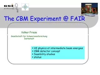
FLUKA SIMULATION OF MUON DETECTOR,MUCH, CBM,FAIR. Bidhan Chandra Mandal 15--17.02.2018. Introduction Description of the set up Simulation/Analysis Results Conclusion. Introduction a) Muon Chamber System (MUCH) is for muon measurement in heavy ion collision

E N D
FLUKA SIMULATION OF MUON DETECTOR,MUCH, CBM,FAIR Bidhan Chandra Mandal 15--17.02.2018
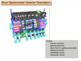
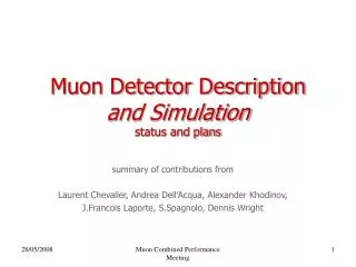
Introduction • Description of the set up • Simulation/Analysis • Results • Conclusion .
Introduction a) Muon Chamber System (MUCH) is for muon measurement in heavy ion collision b) Identify low momentum MUON in high particle density(~0.3 hits/cm2 per central event even at first detector layer) environment c) Track the particle through hadron absorber system d) Absorber detector system is placed downstream to STS e) To reduce meson decays to muon, system is compact f) System consists of 5 hadron absorber layers- iron plates of 16cm & 44 cm (part of 1st Absorber) , 20cm, 20cm and 30 cm, 35 cm. g) Nos. of gaseous (70/30 Ar+CO2) tracking chamber located in triplet behind each iron. Each GEM layer including base is of 38 mm thick h) Reaction rate of 10 MHz is assumed i)Spanning of 500 conical angle j) Proto type chamber based on GEM(gas electron multiplier) technology is working fine at rates of about 1.4 MHz/cm2. k) 30 GeV/c momentum proton beam of point source is assumed to interact Au target.
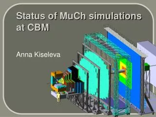
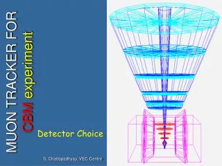
2. Description of the set-up Fe-3 Fe-2 Fe-1 Fe-4 Abs1B Abs1A Graphite STS ( 300µ Si) Au target (-40 cm) Beam Pipe (Al) Pb shield Gas Detector Triplet Stn-1 Stn-2 Stn-3 Stn-4 SECTIONAL VIEW OF MUCH DETECTOR with STS
0.8 1.0 1.4 1.4 Dimentions are in cm SECTIONAL VIEW OF GEM Kit ( Station 1-layer 1,2 & 3 after absorber 1)
Z=190 cm & 190.25 cm (a) (c) Components Materials used Target Au STS stns. Si Beam Pipe Al Abs1a&b Graphite Absorber 2,3,4 Fe Gas Detector, GEM 70/30 Ar-CO2 gas Gas Detector Casing FR4 ( ~ G10) GEM holder Al Magnetic field chosen as 1T uniformly Beam of 30 GeV proton uniform distribution Z=190.05cm (b) SECTIONAL VIEW OF DETECTOR ELEMENT layer 1 (a,b & c)
Nos. of segment 10 overlap 16 nos. 20 nos. 26 nos. 30 nos. Note:-250µ gold foil is used as target. 30 GeV proton beam is considered.
[1] Absorber 1 is divided into 2 parts [see Table1] and is made of graphite. Remaining all 4 absorbers are made of iron. (a) Absorber1 starts at 125 cm from the target. (b) 1st part of Absorber1 is trapezoid ( z position 125-141 cm), 2nd part is parallelepiped (z position 141-185 cm) (c) Magnet shield bars have been removed. (d) Other absorbers are parallelepiped with conical beam pipes. (e) Target is at 40 cm inside the magnet. [2] In the implementation of the parallelepiped, (i) Parallelepiped sides have been calculated using [tan(25°) x (last position of absorber z) +30 cm]. It should be noted that there are 30 cm extra absorber lengths on X and Y sides except the block inside dipole) to keep stations inside the absorbers. Quoted values in the table are calculated taking this additional 30 cm into account. (ii) The beam pipe is conical. [3] For each station, all three layers are of same size. Outer radii of stations are calculated from the last layer taking z(Last Layer)*tan25 shown in column 5 Table 2. Inner radii of stations(active area) are calculated from the 1st layer taking z(1st Layer)*tan5.6 shown in column 4 Table 2. For inclusion of frame, extra 2.5 cm is subtracted from inner radius of station which is shown in column 3 Table2. [4] From z=125 to z=185 cm. Pb shielding is used as a part of the beam pipe.
3. SIMULATION FLUKA CODE FOR 2e6 PARTICLE HISTORY WITH • 30 GeV/c momentum proton beam of point source is interacting on gold target. • Dose is in Gy and expressed for 1MeV neutron equivalent in silicon. • 2.85e+1 (98.3%) GeV particle escaping the system i.e. system simulated without external concrete. • Dose for 1 month in neq/cm2/1month Proton-Au collision ( 1 month of running corresponds to 109 Au ion/s on a 250µ Au target yields 2.6x10¹³ interaction in its 1% nuclear interaction length) • Scoring plane for MUCH system is chosen selectively Without magnetic field means Bx=0,By=0,Bz=0 With magnetic field means Bx=0,By=1 Tesla,Bz=0 • EMFCUT for graphite,Al,Fe & detector gas is taken as 10 MeV • Low neutron,260, downscatter,20 MeV max • Lowdown and lowbias for Absorbers to bean pipes = 7.9852 Mev • All dimensions are in cm
4.Results Without magnetic field With magnetic field Pion radial count vs Φ Pion count vs Z
Muon dose vs Φ Muon radial count vs Φ
Muon count vs Z Photon radial count vs Φ
Photon count vs Z Neutron radial count vs Φ
Neutron count vs Z Electron radial count vs Φ
Electron count vs Z Proton radial count vs Φ
Muon count Pion count Neutron count ( per particle) (per particle) ( per particle) No mag. With Mag. No mag. With Mag. No mag. With Mag. • G101LU to ACD1LU :1.82e-3 1.62e-3 2.18e-2 2.14e-2 NE NE • ACD1LU to G101LU :1.83e-3 1.62e-3 2.18e-2 2.14e-2 NE NE • G101LU to AlB1L1 :3.36e-3 3.9e-3 3.85e-2 3.75e-2 NE NE First station(z=190cm) Layer1 • GF1 to Arc_vac1 :1.35e-4 1.39e-4 1.20e-2 1.20e-2 NE NE • GF1 to BP_0 :1.5e-5 1.69e-5 2.41e-3 2.38e-3 NE NE • GF1 to BL_0 :5.79e-5 5.59e-5 0.143 0.143 NE NE • STS1 to Arc_vac1 :3.87e-4 3.44e-4 2.73e-2 2.69e-2 NE NE • Arc_vac1 to STS1 :3.87e-4 3.51e-4 2.71e-2 2.65e-2 NE NE STS Zone • G102LU to ACD2LU :1.74e-3 1.52e-3 2.00e-2 1.95e-2 6.89e-2 6.88e-2 • ACD2LU to G102LU :1.74e-3 1.52e-3 2.00e-2 1.95e-2 6.90e-2 6.93e-2 • G102LU to AlB1L2 :3.24e-3 2.91e-3 3.52e-3 3.93e-2 0.103 0.104 First station(z=190cm) layer2 • G103LU to ACD3LU :1.65e-3 1.43e-3 1.84e-2 1.79e-2 6.52e-2 6.63e-2 • ACD3LU to G103LU :1.65e-3 1.44e-3 1.83e-2 1.79e-2 6.62e-2 6.72e-2 • G103LU to AlB1L3 :3.12e-3 2.77e-3 3.23e-2 3.15e-2 9.62e-2 9.70e-2 First station(z=190cm) layer3 • G104LU to ACD4LU :8.75e-4 8.19e-4 5.67e-3 5.39e-4 4.13e-2 4.11e-2 • ACD4LU to G104LU :8.75e-4 8.20e-4 5.66e-3 5.38e-4 4.16e-2 4.15e-2 Second station(z=200cm) layer1 NE = Not evaluated
Expected fluence is as below Pion fluence : 400 kHz/cm2 at the first station 1st layer as per result :1.27 kHz/cm2 Muon count Pion count ( per particle) (per particle) • No mag. With Mag. No mag. With Mag. So, first station (@1e9 p/s) :0.106 :1.27 (1st layer fluence in kHz/ cm2 ) 10x106 p/s interaction rate on target @1% interaction length i.e. 109 p/s proton source of 30 GeV Total area of GEM station 1 Layer1 = 16 x 1068.50 = 170.96e2 cm2 Total area of GEM station 1 Layer2 = 20 x 1110.98 = 222.19e2 cm2 Total area of GEM station 1 Layer3 = 26 x 1563.78 = 406.58e2 cm2 Total area of GEM station 2 Layer1 = 30 x 1995.87 = 598.76e2 cm2 No mag. With Mag. • Dose in Zone G101LU+ACD1LU+AlB1L1(GeV/gm/part):5.27e-3 x (10x10x10) 4.79e-3 x (10x10x10) (Gy/part) :8.45e-7 7.67e-7 Si1MeVNE ( new/cm2/particle) 1.0050e3 1.0078e3 Si1MeVNE ( new/cm2/1 month) 2.602e18 2.61e18 Energy deposited in GeV/particle ( zone wise) • Blk :2.86e1 2.86e1 • ACD1LU :1.59e-3 1.41e-3 • G101LU :1.51e-3 1.45e-3 • ACD1LD :2.39e-4 2.29e-4 • G101LD :1.28e-3 1.26e-3 • AlB1L1 :.3.41e-3 3.19e-3 • ACD2LU :3.4e-4 3.13e-4
5. Conclusion • Muon a MIP, detection is feasible in this SIS-100B setup. • MUCH Simulation geometry needs further modification for shielding ( may be concrete), geometrical dimensions , fabrication as well as other interfaces feasibility • Other particle (Kaon, pion, proton, electron etc.) presence is ignorable. • Magnetic field of 1 T contributes difference to MUON count. • Interaction is reasonable for the GEM read out • Doses distribution are addressed for detectors’ element sustainability • Heat load on components needs attention for cooling. Thanks. Ref.: • Technical design report for the CBM, GSI Report 2013-4, Oct2013 • A GEM based Muon Tracker for CBM experiment at FAIR by Anand K Dubey, Proceedings of the DAE Symposium on Nucl. Phys. 57(2012) • FLUKA respin 2011.2c.6.