Download
1 / 40
870 likes | 1.82k Views
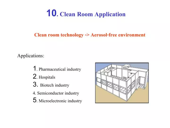
10. Clean Room Application. Clean room technology -> Aerosol-free environment. Applications:. 1. Pharmaceutical industry 2. Hospitals 3. Biotech industry 4. Semiconductor industry 5. Microelectronic industry. Examples. }. Sources of contamination. 1. Aerosol -> airborne particles

E N D
10. Clean Room Application Clean room technology -> Aerosol-free environment Applications: 1. Pharmaceutical industry 2. Hospitals 3. Biotech industry 4. Semiconductor industry 5. Microelectronic industry
} Sources of contamination 1. Aerosol -> airborne particles 2. Hydrosol, e.g., control of deionized water and other process chemicals 3. Biological contaminants, e.g., pyrogenic and endotoxin producing bacteria 4. Ionic and radioactive components 5. Condensation or diffusive products 6. Chemically reactive particles Won’t be considered!
The Principles of a Clean Room 1. The air supplied to the CR is sufficient in quantity to dilute and remove the contamination generated in the room. 2. The air within the cleanroom moves from clean to less-clean areas and moves in the correct direction through doorways. 3. The air supplied to the room is of sufficient quality that it will not add to the contamination of the room. 4. The air movement in the room should insure that there are no areas in the room of high concentration of contamination. 5. If all other principles are met then the concentration of particles should be measured to test if the room meets the required standard.
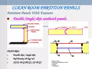
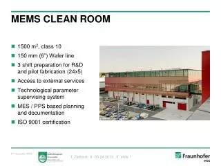
Design 1. Room is supplied with large quantities of highly filtered air. 2. This air dilutes and removes the particles and bacteria dispersed from personnel and machinery in the room. 3. Also this holds positive pressure and ensures that air only flows out of the room. 4. Room is built from materials that do not generate particles and can be easily cleaned.
Positive Isolation Schematic A/C 3001X Blank supplies or Terminal HEPAs Make Up Air Optional Filter Integrated to A/C 3001X Optional Floor A/C Return
Negative Pressure (TB) Isolation Room Schematic A/C Exhaust Bathroom exhaust tied into the exhaust ducting. Pre filter should be accessible from room. Main filter housed in module that is removed and accessed above ceiling. Term HEPA Supplies A/C Supply 3 TOTAL Return Annunciator
5. Cleanroom personnel wear clothing which minimizes their dispersion of particles 6. Two major types of cleanrooms: Unidirectional (laminar flow) and turbulently ventilated. 7. Unidirectional uses much more air than turbulent.
8. Unidirectional CR air speed is typically about 0.4m/s. 9. Air is recirculated at a great rate, diluted with some fresh air and some is discarded. 10. Pencils cause graphite particles! 11. 2-10% of total air supply is fresh air.
1. HEPA FILTERS High Efficiency Particulate Air filters are replaceable extended-media dry-type filters in a rigid frame having a minimum particle collective efficiency of - 99.97 percent for a 0.3 micron particle (standard grade) - 99.90 percent for a 0.3 micron particle (low grade) - 99.99 percent for a 0.3 micron particle (high grade) and a maximum clean filter pressure drop of 2.54 cm (1") water gauge when tested at rated air flow capacity. 2. ULPA FILTER Ultra Low Penetration Air filters are extended media dry filters in a rigid frame that have a minimum particle collection efficiency of 99.999 percent for particles greater than or equal to 0.12 micron in size
1. Average person in poor CR garments (coats) generates about 2x10⁶ part/min greater than 0.5 mm and 300000 part/min > 5.0 mm. 2. For cleanrooms of ISO class 6 (class 1000) and poorer quality, HEPA filters are used with turbulent ventilation to meet the cleanroom classification. 3. For cleanrooms of ISO class 5 (class 100), HEPA filters are used with unidirectional ventilation to meet the cleanroom classification. 4. For cleanrooms of ISO class 4 (class 10) or lower, ULPA filters are used with unidirectional ventilation to meet the cleanroom classification.
5. Pressure drop across a filter is obviously dependant on the velocity of air through the filter. The nominal air velocity is usually considered to be 0.5 m/s (100ft/min) and pressure drop at this velocity is likely to be between 120-170 Pa. 6. When the pressure drop reaches 2.5-3 times the original pressure, its time to replace the filters.
Filter Collection Mechanism - A Review 1. Diffusion: tiny particles which don’t have enough mass to leave the air stream on their own move randomly in the air stream. This random motion is due to collisions with other small dust particles and collisions with the molecules of the gas which they are suspended. If these particles touch a fibre or previously captured particles they will be held. (Brownian movement causes them to move randomly)
2. Impaction is when more massive particles leave the air stream due to their own inertia and collide with a fibre. This will cause them to be imbedded.
3. Interception is when a particle strikes a fiber as it passes (tangentially). The particle will also be captured in this process.
Electrically Enhanced Filtration Filter becomes bactericidal!
Flow enters first high intensity ionizing field.
Particles and bacteria are charged due to ion flux in this ionizing field - some of the bacteria are killed here.
The charged particles and bacteria are highly efficiently filtered - up to 1000 times lower penetration than conventional filters with the same pressure drop and flow rate.
Bacteria caught on the filter are subjected to a continuous dose of ionizing radiation and are thus killed.
Filter Testing Military standard 282 1. Thermally generated particles of di-octyl phthalate (DOP) with average size of 0.3 micron. Nowadays poly-alpha olefin(PAO) or di octyl sebacate(DOS) have replaced DOP. 2. Oil mist is produced upon heating these oils. 3. Efficiency is then measured directly. Sodium flame test (Eurovent 4/4) 1. An aerosol of sodium chloride is sprayed into the air then sucked through the filter 2. The efficiency is tested.
Clean Room Measurements Clean room limits: U.S. (209D) and Germany Standards (VDI 2083)
Recommended time intervals for regular particle measurements in various clean room classes
Minimize sampling loss 1. Short sampling tubes. 2. Non-conductive material for the tubings. Avoid polymeric materials. 3. Isokinetic sampling is not possible due to turbulence and it may not be necessary. Sampling points 1. Distributed uniformly in clean room. 2. Distance between points should not be larger than 2 m. 3. Minimum number of sampling points from US Fed Std 209D: - Area of the entrance plane divided by 25 ft2, or - Area of the entrance plane divided by the square root of class designation. 4. Height of the sampling should be at the working or product level.
Minimum volume per sampling in liter per minute: US Fed Std 209D
Monotoring Systems 1. Monitor ambient air and within the equipment. 2. Sensor system is needed to give a feedback to the control system to prevent deposition on the product. 3 Aim of clean-room monitoring - To gain information about the process - To determine the interdependence of different parameter - To elucidate the cause of low product quality - To determine the effects of any actions on product yield.
Measurement Techniques Optical Particle Counters (OPC) Light scattering
Angular scattering for water droplet (m = 1.33). Spectral scattering for water droplet (m = 1.33).
Principle of CPC - CPC uses the principle that supersaturated vapor condenses on small particles. - An internal pump draws the aerosol sample into the CPC. - A flowmeter controls the flow volumetrically. - Upon entering the instrument, the sample passes through a heated saturator, where butanol evaporates into the air stream and saturates the flow. - The aerosol sample then passes into a cooled condenser tube,where vapor supersaturates and condenses onto the airborne particles. - This produces larger, easily detectable aerosol droplets. - These droplets pass through an optical detector immediately after leaving the condenser.
Principle of PFM - No sample is taken. Light is introduced to measurement volume. - Otherwise functions like an OPC. - Three types of PFM 1. Beam expansion: Laser beam is expanded by cylindrical lenses to form a rectangular beam. 2. Multiple reflection: Light sheet is produced by multiple reflection of a laser beam between two mirrors. 3. Scanner: Laser beam is deflected by a polygon mirror.