Download
1 / 72
720 likes | 805 Views
Division of Mines. DMME. Ventilation Section. Outline. Airflow Measurements How to take air readings Measuring areas Mean Entry Velocity Principals of Airflow When and Where to take Air Measurements Actions for Excessive Methane. Three categories of Airflow Measurements.

E N D
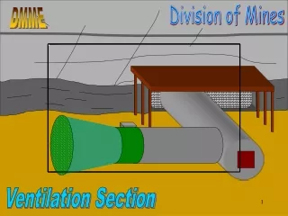
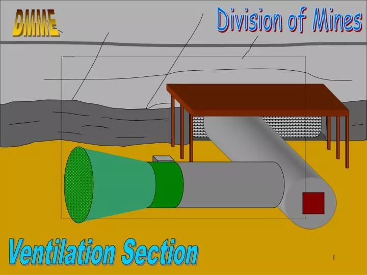
Division of Mines DMME Ventilation Section
Outline • Airflow Measurements • How to take air readings • Measuring areas • Mean Entry Velocity • Principals of Airflow • When and Where to take Air Measurements • Actions for Excessive Methane
Three categories of Airflow Measurements • Low Velocity (0 to 120 fpm) • Medium Velocity (120 to 2000 fpm) • High Velocity (>2000 fpm)
0 90 10 AVIS INSTRUMENT MFG CO BALTIMORE MARYLAND M A D E IN U S A 80 20 0 0 900 100 9000 1000 200 800 8000 2000 70 30 7000 700 300 3000 6000 600 400 4000 5000 500 40 60 STANDARD 50 The principal mechanism for taking medium air velocity measurement is the Anemometer. A high speed anemometer is most often used for high velocity air measurements!
Taking Anemometer Measurements • Make sure to zero dial! • Make sure air flow is into the back of the anemometer. • Press lever to start dial movement. • Take reading for 1 Minute. • Press lever to stop. • For precise measurements, use a wand or extension rod to minimize effects of hand, arm, and body.
Traverse the whole entry when taking an anemometer reading. 60 Sec. Start End 45 Sec. 15 Sec. 30 Sec.
0 0 90 90 10 10 AVIS INSTRUMENT MFG CO BALTIMORE MARYLAND AVIS INSTRUMENT MFG CO BALTIMORE MARYLAND M A D E IN U S A M A D E IN U S A 80 80 20 20 0 0 0 0 900 900 100 100 9000 9000 1000 1000 200 200 800 800 8000 8000 2000 2000 70 70 30 30 7000 7000 700 700 300 300 3000 3000 6000 6000 600 600 400 400 4000 4000 5000 5000 500 500 40 40 60 60 STANDARD STANDARD 50 50 Take care to record correct dial reading. Dial Reading = 239 feet per minute.
SN # 0000 SN # 0000 Date Due Recal 07/15/99 Date Due Recal 07/15/99 VEL CORR 50 49 100 47 150 45 200 44 250 42 300 40 400 37 500 33 600 34 700 36 800 39 900 41 1000 45 VEL CORR 50 49 100 47 150 45 200 44 250 42 300 40 400 37 500 33 600 34 700 36 800 39 900 41 1000 45 Correct reading per correction chart. Dial Reading = 239 Correction factor = +43 Velocity = 282 Note Calibration Due Date
5’ 0” 5’ 0” 6’ 6” Take multiple height measurements for irregular roof. Average Height = 5’ 6”
Estimate Gob Areas. Triangular shaped gob 3 Feet 4 Feet Gob area = 1/2 * 3 *4 = 6 feet2
Estimate area of obstruction! Taking air reading between 3 rows of cribs. You have to estimate the effect of the cribs. Crib area = 3 * 2.5 * 6 * 50% = 22.5 feet2
Air velocity has an impact on the amount of obstructions you should consider! Narrow, high velocity openings may require you to take out the area of your body! Remove 3 feet2 for body and 3 feet2 for timber!
20’ 5’ 0” 5’ 0” 6’ 6” 3 Feet 4 Feet Calculations Example Gob area = 1/2 * 3 *4 = 6 feet2 Q = V A Average Height = 5’ 6” Area = 5.5 X 20 - 6 = 110 ft.2 - 6 ft.2 = 104 ft.2 Q = V A = 282 X 110 = 31,020 cfm
Recommended locations to take air readings. Take Air Readings Upwind of Obstructions! Regulator Try to take air readings a few feet inby corners.
O.67 ft.2 1.33 ft.2 If cannot take air reading upwind of regulator then take centerline reading in regulator and multiply by 0.9. Anemometer Reading = 100 fpm Velocity =100 X 0.9 = 90 fpm Area of block = 0.67 X 1.33 = 0.89 ft.2 Area of Reg. = 8 X 0.89 = 7.2 ft.2 Q = 90 X 7.2 = 648 cfm
Divide distance traveled by time required to get the velocity. Multiply by 60 to get fpm. How to take smoke readings! It takes two! Best for upstream (smoker) to look down path of smoke with light. Measure how long it takes smoke to travel over a pre-determined distance! Example: 6 seconds to travel 10 feet. 10/6 = 1.67, 1.67 X 60 = 100 fpm
1 4 7 2 5 8 3 6 9 Divide the entry into quadrants to take smoke readings. The number of quadrants is flexible! OR take centerline reading and multiply by 0.9!
4 ft. 16 Ft. 5 ft. Mean Entry Velocity 4 X 5 = 20 Ft.2 272 X 20 = 5,440 cfm 1) Measure area behind curtain. 3) Calculate airflow behind curtain. 5,440/80 = 68 fpm 5) Divide airflow reading behind curtain by entry area. 2) Take anemometer reading behind curtain. 4) Measure remaining area of entry. Velocity = 272 fpm 16 X 5 = 80 Ft.2
R2 Area = = 3.14 Pie are square! Ventilation Tubing Area
Area = 3.14 X 12 Area = 3.14 ft.2 R2 Area = 5 ft. 20 ft. Vent Tubing Example Q=VA Q=3.14 X 2,350 Q=7,379 cfm 24 inch Diameter Tubing Anemometer reading = 2,350 fpm Entry Area = 5 X 20 - 3.14 = 97 ft.2 Mean Entry Velocity = 7,379/97 = 76 fpm
Airflow in a mine is induced by pressure differences between intake and exhaust openings.
Exhausting Fan The pressure difference is caused by imposing some form of pressure at one point or a series of points in the ventilating system.
The pressure created must be great enough to overcome frictional resistance and shock losses. • Friction pressure losses are caused by the resistance of the walls on the airstream. Friction losses therefore depend upon the conditions and roughness of individual wall surfaces and velocity of air. • Shock pressure losses are caused by abrupt changes on the velocity of air movement. Shock losses therefore are the result of changes on air direction or of airway areas, obstructions, and regulation.
R Passageways, both intake and returns must be provided to conduct airflow
Airflow follows a square-law relationship between volumes and pressures, that is, twice the volume requires four times the pressure. 100,000 CFM 200,000 CFM 2 inches W.G. 8 inches W.G.
The pressure drop for each split leaving from a common point and returning to a common point will be the same regardless of the air quantity flowing in each split. A B R
Mine ventilation pressures, with respect to atmospheric pressures, may be either positive (blowing) or negative (exhausting). • Total Pressure = Static Pressure + Velocity Pressure • Static Pressure is the pressure exerted in all directions. Tire pressure is static pressure. Can be negative or positive. • Velocity pressure is directional pressure. You feel velocity pressure when you feel the wind. VP is always positive. • Exhausting fans are generally rated on Static Pressure. • Blowing fans are generally rated on Total Pressure.
Air always flows from a point of higher to lower pressure. • Blowing fans create a high pressure point immediately inby the fan. Air travels from this high point through the mine to the surface. • Exhausting fans create a low pressure point immediately inby the fan. Air travels from the surface through the mine to this low pressure point.
Blowing Fan • Neutral flows to outside. Smoke will not travel to face area. • Gobs are “pressurized”. Less influx of contaminants from gobs until fan stops. • Harder to maintain required LOC quantities. • Best for mining near OLD WORKS.
Exhausting Fan • Neutral flows toward face. Smoke will travel toward face area. • Gobs are “under suction”. Contaminants flow from gobs until fan stops. • Easier to maintain required LOC quantities. • Worse for mining near OLD WORKS.
Face Ventilation Blowing Exhausting • Higher velocity at face. • Best for gas. • Worse for dust. • Lower velocity at face. • Worse for Gas. • Good for Dust.
? Where to take air readings?
Section 45.1-161.208. Pre-shift Examinations.C. During the pre-shift examination, the mine foreman shall determine the volume of air entering each of the following areas if a miner is scheduled to work in the areas during the oncoming shift: • In the last open crosscut, which means the crosscut in the line of pillars containing the permanent stoppings that separate the intake and return air courses, of each set of entries or rooms on each working section and areas where mechanized mining equipment is being installed or removed.
Section 45.1-161.209. On-shift Examinations.C. Persons conducting the on-shift examination shall determine at the following locations which are underground: • The volume of air in the last open crosscut, which means the crosscut in the line of pillars containing the permanent stoppings that separate the intake and return air courses, of each set of entries or rooms on each working section and areas where mechanized mining equipment is being installed or removed.
LOC Where is Last Open Crosscut? R
LOC LOC Where is Last Open Crosscut? R
Section 45.1-161.210. Volume of Air. • The quantity of air passing through the last open crosscut shall be not less than 9,000 cubic feet per minute; provided, however, that the quantity of air reaching the last open crosscut in pillar recovery sections may be less than 9,000 cubic feet per minute, if at least 9,000 cubic feet of air per minute is being delivered to the intake end of the pillar line. • The air current at working faces shall under all conditions have a sufficient volume to readily dilute and carry away smoke from blasting and any flammable or harmful gasses.
Where is Last Open Crosscut? LOC LOC
LOC Where is Last Open Crosscut?
Section 45.1-161.208. Pre-shift Examinations.C. During the pre-shift examination, the mine foreman shall determine the volume of air entering each of the following areas if a miner is scheduled to work in the areas during the oncoming shift: • The volume of air at the intake end of any pillar line • where a single split of air is used, in the intake entry furthest from the return air course, immediately outby the first open crosscut outby the line of pillars being mined, or • if a split system is used, in the intake entries of each split immediately inby the split point.
Section 45.1-161.209. On-shift Examinations.C. Persons conducting the on-shift examination shall determine at the following locations which are underground: • The volume of air at the intake end of any pillar line • where a single split of air is used, in the intake entry furthest from the return air course, immediately outby the first open crosscut outby the line of pillars being mined, or • if a split system is used, in the intake entries of each split immediately inby the split point.
Intake Where is Intake End of Pillar Line?
Inby Inby Where is immediately inby Split Point?
Where is Last Open Crosscut? LOC LOC
LOC LOC LOC LOC Where is Last Open Crosscut?
Section 45.1-161.208. Pre-shift Examinations.C. During the pre-shift examination, the mine foreman shall determine the volume of air entering each of the following areas if a miner is scheduled to work in the areas during the oncoming shift: • On each longwall or shortwall in the intake entry or entries at the intake end of the longwall or shortwall face immediately outby the face and the velocity of air at each end of the face at the locations specified in the approved ventilation plan required by the federal mine safety law...
Section 45.1-161.209. On-shift Examinations.C. Persons conducting the on-shift examination shall determine at the following locations which are underground: • The volume of air on a longwall or shortwall, including areas where longwall or shortwall equipment is being installed or removed, in the intake entry or entries at the intake end of the longwall or shortwall. • The velocity of air at each end of the longwall or shortwall face at the locations specified in the approved ventilation plan required pursuant to the federal mine safety law;
Volume Velocity locations as required by approved federal ventilation plan. Velocity Where are Intake Air Readings required?
Volume Velocity locations as required by approved federal ventilation plan. Velocity Where are Intake Air Readings required?