Download
1 / 14
140 likes | 279 Views
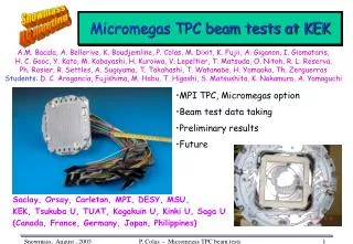
Micromegas TPC Beam Test Result. Motivation Micromegas TPC Setup Preliminary Results Summary. H.Kuroiwa (Hiroshima Univ.) Collaboration with Saclay, Orsay, Carlton, MPI, DESY, MSU, KEK, Tsukuba U, TUAT, Kogakuin U, Kinki U, Saga U.

E N D
Micromegas TPC Beam Test Result Motivation Micromegas TPC Setup Preliminary Results Summary H.Kuroiwa (Hiroshima Univ.) Collaboration with Saclay, Orsay, Carlton, MPI, DESY, MSU, KEK, Tsukuba U, TUAT, Kogakuin U, Kinki U, Saga U The 8th ACFA Workshop on Physics and Detector at the Linear Collider Jul. 12, 2005, EXCO, Daegu, Korea
Motivation • Comparison of several sensors using same Field Cage, Electronics, analysis • MWPC : Beam test in Jun, 2004 • GEM : Beam test in Apr, 2005 • Micromegas Previous talk Beam test in Jun. 22~Jul. 1, 2005 We try to understand Micromegas TPC performance
S1 s S2 Micromegas 50μm • Micromesh supported by 50-100μm - high insulating pillars • Multiplication takes place between the anode and the mesh • One stage • Direct detection of avalanche electrons • Small E×B effect • Fast signals • Self-suppression of positive ion feedback the ions return to the grid • Better spatial resolution • No wire angular effect
TPC • Length of FC : 26 cm • Pad • 2×6 mm, 0.3mm gap • 32 pads×12 pad rows ⇒ 384 readout channels • Non-staggered • Pad plane : 10×10cm • Readout • ALEPH TPC electronics 24 amplifiers, 16 channels each 500ns shaping time, charge sensitive sampled every 80 ns digitized by 6 TPDs
55Fe 6keV Escape 3keV Mesh Signals • There is a 55Fe source attached on the back of the cathode plane to monitor Micromegas stability by looking at mesh signals (Readout by a multi channel analyzer MCA 8000 from Amptek) Ar + 5%isobutane
Experimental Setup • KEK-PS π2 beam line • 4GeV π- • Super conducting magnet (JACEE) • B = 0, 0.5 and 1T • Gas • Ar + isobutane (95:5) vd = 4.18cm/μsec at 220V/cm
Preliminary Results Charge Distribution Pad Response X Resolution Z Resolution • Analysis • Double fit (developed at DESY)
charge distribution at Row6 as a function of Z Charge Distribution • Charge distribution (B = 1T) • For 12 rows Edge effect Edge effect We saw no significant attenuation
Pad Response Function Charge width for different drift regions (B = 0T) anode Z → is evaluated by a normalized charge (NQi = Qi/∑Q) on pad i, as a function of (Xpad - Xtrack) cathode Distribution becomes wider at longer drift distance
Width of PRF as a function of Z B = 0T Preliminary results B = 0.5T B = 1T Measured CD in good agreement with Mag. Simulation
X Resolution as a function of Z Row6 + Row7 Cd = Cd(PRF) Cd fixed for each B Preliminary results
X Resolution (How to Fit?) σ0 : resolution w/o diffusionCd : diffusion constantNeff : effective number of electrons Other Diffusion 1- fix Cd from PRF 2- fit σx = f(z) with σ0and Neff free 3- Plot Magboltz curve with :σ0obtained from the fit (2)Cd is known Neff from (2)
Z Resolution as a function of Z B = 0T • σz ⋍ 500μm at 0.5T Preliminary results B = 0.5T B = 1T Unlike σX, σZ has no significant B-dependence
Summary • To measure Micromegas TPC performance • We did the beam test at KEK-PS π2 beam line using 4GeV neg. pions in magnetic field • Micromegas in TPC worked stably Measured diffusion constants are consistent with Mag. simulation σx ⋍ 200μm , σz ⋍ 800μm at 1T • But these results are still very preliminary