Download
1 / 15
160 likes | 303 Views
A Comparative Study of Radar Stereo and Interferometry for DEM Generation. M. Gelautz (1) , P. Paillou (2) , C. Chen (3) , and H. Zebker (4) (1) Vienna University of Technology, Vienna, Austria (2) Observatoire Astronomique, Bordeaux, France (3) JPL, Pasadena, CA (4) Stanford University, CA

E N D
A Comparative Study of Radar Stereo and Interferometry for DEM Generation M. Gelautz(1), P. Paillou(2), C. Chen(3), and H. Zebker(4) (1)Vienna University of Technology, Vienna, Austria (2)Observatoire Astronomique, Bordeaux, France (3)JPL, Pasadena, CA (4)Stanford University, CA Email: gelautz@ims.tuwien.ac.at
Introduction and Motivation • Growing availability of interferometric and stereoscopic (multi-incidence angle) data sets from single and multiple sensors. • Most existing studies utilize either stereo or interferometry exclusively – do not provide a direct comparison of the two techniques in application to one and the same test site.
Technique Review:Stereo and Interferometry Fig1. Imaging geometry.
Test Site and Data Set • Asal Rift, Republic of Djibouti, East Africa. • Spot reference DEM derived from optical stereo analysis and topographic maps. • ERS-2 interferometric image pair (raw). • Radarsat stereo image pair & Radarsat interferometric image pair (SLC).
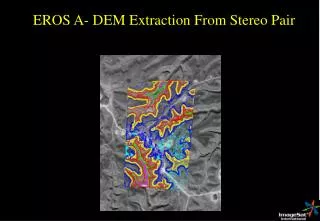
Radarsat Stereo Image Pair (a) 28° [std2] (b) 37° [std4] Fig2. SAR stereo pair of the Asal Rift test site (~260 km2), illuminated from the right.
Radarsat Interferometric Data Set (a) Interferogram (after flattening) (b) Coherence map Fig3. Radarsat InSAR data acquired during descending orbits (24 days temporal baseline, 54 m height ambiguity.)
ERS-2 Interferometric Data Set • Magnitude image (b) Interferogram (after flattening) (c) Coherence map Fig4. ERS-2 InSAR data acquired during ascending orbits (35 days temporal baseline, 17 m height ambiguity.)
Algorithms • Stereo Matching • Correlation-based matcher with edge-based pre-processing. (PAILLOU, P., and GELAUTZ, M., 1999, Relief reconstruction from SAR stereo pairs: the "optimal gradient" matching method. IEEE Transactions on Geoscience and Remote Sensing, 37, 2099-2106.) • Phase Unwrapping • Dynamic-cost cycle-canceling (DCC) (CHEN, C., and ZEBKER, H., 2000, Network approaches to two-dimensional phase unwrapping: intractability and two new algorithms. Journal of the Optical Society of America A, 17, 401-414.) • DEM Merging • Averaging algorithm employs a filtered coherence map along with user-defined weights.
DEM Reconstruction SPOT reference DEM Radarsat stereo DEM Stereo/InSAR merged DEM ERS-2 interferometric DEM
Difference DEMs InSAR Merged Stereo Radarsat ERS-2
Stereo/InSAR Error Histograms:ERS-2 / Radarsat Fig5. Error histograms of ERS-2 InSAR, Radarsat stereo, and merged DEM.
Scatter Plots:Height Error vs. Coherence ERS-2 InSAR Radarsat Stereo Merged DEM
Summary • The more robust stereo reconstruction was able to capture the general terrain shape, but finer surface details were lost. • In regions of high coherence, the interferometric DEMs were of much better quality than the stereo result. • Pronounced interferometric phase unwrapping errors could be suppressed by combining the stereo and InSAR results.
Acknowledgements • This study was performed under the ERS AO3-245 project. • The Radarsat data were provided by ADRO-373.