Download

1 / 78
970 likes | 1.72k Views
Inverse Dynamics. What is “Inverse Dynamics”?. What is “Inverse Dynamics”?. Motion – kinematics Force – kinetics Applied dynamics. What is “Inverse Dynamics”?. Inverse Dynamics. Using Newton’s Laws Fundamentals of mechanics Principles concerning motion and movement

E N D
What is “Inverse Dynamics”? • Motion – kinematics • Force – kinetics • Applied dynamics
Inverse Dynamics • Using Newton’s Laws • Fundamentals of mechanics • Principles concerning motion and movement • Relates force with motion • Relates moment with angular velocity and angular acceleration
Inverse Dynamics • Newton’sLaws of motion • 1st: • 2nd: • 3rd: a given action creates an equal and opposite reaction
Inverse Dynamics • If an objectisatequilibriatedrest = static • If an objectis in motion = dynamic • If objectaccelerates, inertial forces calculatedbased on Newton’s 2nd Law (ΣF = ma)
Dynamics • Twoapproaches to solve for dynamics
Dynamics • Direct method • Forces are known • Motion iscalculated by integrating once to obtainvelocity, twice to obtaindisplacement
Dynamics • Inverse method • Displacements/motion are known • Force is calculated by differentiating once to obtain velocity, twice to obtain acceleration
Objective • Determine joint loading by computing forces and moments (kinetics) needed to produce motion (kinematics) with inertial properties (mass and inertial moment) • Representative of net forces and moments at joint of interest
Objective • Combines • Anthropometry: anatomical landmarks, mass, length, centre of mass, inertial moments • Kinematics: goniometre, reflective markers, cameras • Kinetics: force plates
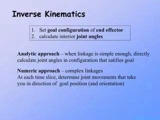
1st Step Establish a model
1st Step • Establish the model • Inertial mass and force often approximated by modelling the leg as a assembly of rigid body segments • Inertial properties for each rigid body segment situated at centre of mass
Segmentation • Assume • Each segment issymmetric about its principal axis • Angularvelocity and longitudinal acceleration of segment are neglected • Frictionless
2ndStep • Measure ALL externalreaction forces • Appoximateinertialproperties of members • Locate position of the common centres in space • Free body diagram: • forces/moments at joint articulations • forces/moments/gravitational force at centres of mass
Free Body Diagram • Statics – analysis of physicalsystems • Staticallydeterminant
3rdStep • Staticequilibrium of segments • Forces/moments knownat foot segment • Using Newton-Euler formulas, calculationbeginsat foot, then to ankle • Proceedfrom distal to proximal UNKNOWNS KNOWNS
FBD of Foot Triceps sural force • $%#&?! • Multiple unknowns Bone force Anterior tibial muscle force Joint moment Fg Centre of pressure Ligament force Centre of gravity
Simplify • Multiple unknown force and moment vectors • Muscles, ligaments, bone, soft tissues, capsules, etc. • Reduction of unknownvectors to: • 3 Newton-Euler equilibriumequations, for 2-D (Fx, Fy,Mz) • 6 equations, for 3-D (Fx, Fy,Fz,Mx,My,Mz) • Representativeof net forces/moment
Simplification • Displace forces to joint centre • Force equal and opposite F* Force at joint centre Fr Centre of pressure F Foot muscle forces -F* Force equal and opposite Centre gravity
Simplification • Replace coupled forces with moment F* Force at joint centre Fr Centre of pressure F Foot muscle force -F* Force equal and opposite Centre of gravity M Moment
Simplification • Representation net moments and forces atankle • cm = centre of mass • prox = proximal • dist = distal Mankle rcm,prox Fankle xankle, yankle rcm,dist Freaction xreaction, yreaction mfootg
3rdStep Fa Unknown forces/moments atankle • f = foot • a = ankle • r = reaction • prox = proximal • dist = distal Ma Ifαf mfaf mfg Tr Fr Force/moment known (force plate)
3rdStep • Therefore, ankle joint expressed by:
3rdStep • Thus, simply in 2-D : • Much more complicated in 3-D!
3rdStep • Moment is the vectorproduct of position and force • NOT a direct multiplication
3rdStep • Ankle force/moment applied to subsequent segment (shank) • Equal and opposite force at distal extremity of segment (Newton’s 3rd Law) • Next, determineunknownsat proximal extremity of segment (knee) UNKNOWNS h h KNOWNS
3rdStep • Knee joint isexpressed by: • k = knee • s = shank • a = ankle • cm = centre of mass • prox = proximal • dist = distal
3rdStep • Knee forces/moments applied to subsequent segment (thigh) • Equal and opposite force at distal extremity of segment (Newton’s 3rd Law) • Next, determineunknownsat proximal extremity of next segment (hip) UNKNOWNS KNOWNS
3rdStep • Hip joint isexpressed by: • k= knee • h = hip • t = thigh • cm = centre of mass • prox = proximal • dist = distal
Exercise • Calculate the intersegment forces and moments at the ankle and knee • Groundreaction forces Fr,x = 6 N Fr,y = 1041 N • Rigid body diagramsrepresent the foot, shank, and thigh • Analyse en 2-D thigh shank y Fr,x = 6 N x Fr,y = 1041 N
Exercise 0.5 m 0.02 m knee 0.34 m 0.06 m CMshank 0.12 m 0.10 m ankle 0.09 m 0.04 m 0.03 m CMfoot Fr,x Fr,y
Exercise thigh thigh shank shank foot foot Fr,x = 6 N Fr,x = 6 N Fr,y = 1041 N Fr,y = 1041 N
Exercise Fs,prox,y Ms,prox Fs,prox,x Fa,y msas,y mfaf,y Iα Ma msas,x Fa,x Iα msg mfaf,x Ms,dist Fs,dist,x mPg Fs,dist,y Fr,x = 6 N foot shank Fr,y = 1041 N
Exercise– ankle(F) Fa,y Ma -0.56 m/s2 Fa,x Iα -0.36 m/s2 mfg ankle = (0.10, 0.12) CMfoot = (0.04, 0.09) CP = (0.0, 0.03) Fr,x = 6 N Fr,y = 1041 N
Exercise – ankle(M) Fa,y Ma -0.56 m/s2 Fa,x Iα -0.36 m/s2 mfg ankle = (0.10, 0.12) CMfoot = (0.04, 0.09) CP = (0.0, 0.03) Fr,x = 6 N Fr,y = 1041 N
Exercise– knee(F) Fs,prox,y Ms,prox Fs,prox,x -1.64 m/s2 Iα 1.56 m/s2 msg 102.996Nm 6.36 N 1031.75N ankle = (0.10, 0.12) CMshank = (0.06, 0.34) knee = (0.02, 0.77)
Exercise– knee(M) Fs,prox,y Ms,prox Fs,prox,x -1.64 m/s2 Iα 1.56 m/s2 msg 102.996Nm 6.36 N 1031.75N ankle = (0.10, 0.12) CMshank = (0.06, 0.34) knee = (0.02, 0.77)
Recap • Establish model/CS • GRF and locations • Process • Distal to proximal • Proximal forces/moments OPPOSITE to distal forces/moments of subsequent segment • Reaction forces • Repeat
Principal Calculations 2-D 3-D
3-D • Calculations are more complex – joint forces/moments stillfrom inverse dynamics • Calculations of joint centres – specific marker configurations • Requires direct linear transformation to obtain aspect of 3rd dimension
3-D • Centre of pressure in X, Y, Z • 9 parameters: force components, centre of pressures, moments about each axis • Coordinate system in global and local
3-D – centre of pressure • M= moment • F = reaction force • dz = distance between real origin and force plate origin • T = torsion • * assumingthat ZCP= 0 • * assumingthatTx=Ty = 0 direction
Global and Local CS Z = +proximal GCS = global coordinate system X = +lateral LCS = local coordinate system Y = +anterior
Transformation Matrix • Generate a transformation matrix – transforms markers from GCS to LCS • 4 x 4 matrix combines position and rotation vectors • Orientation of LCS is in referencewith GCS