Download
1 / 8

E N D
1. Timer IC Unit Operation By:
Diana Mae G. Cubillas
ICS 30 A
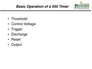
2. Timer IC The figures above is the 555 timer, an analog-digital IC. As described in the figures, it is made of linear comparators and digital flip-flops.
The one on the left is the internal of the IC and the one on the right is its external view.
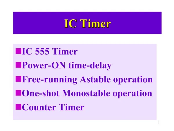
3. Operational Modes One-Shot Mode (Monostable Multivibator)
Has a single stable state, which is off state
Generates a single pulse of a fixed time duration each time it receives an input trigger pulse Astable Multivibrator (Clock Circuit)
Simply an oscillator
Generates a continuous stream of rectangular off-on pulses that switch between two voltage levels
4. Monostable Multivibrator
5. Uses of One-Shot Mode turning some circuit or external component on or off for a specific length of time
generate delays
6. Astable Operation
7. Formula Difference Astable operation
Thigh = 0.7 (ra + rb)c
Tlow = 0.7rbc
t = Thigh + Tlow Monostable operation
Thigh = 1.1 ra c
8. Waveforms of Astable Operation
9. Waveforms of Monostable Operation