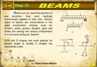
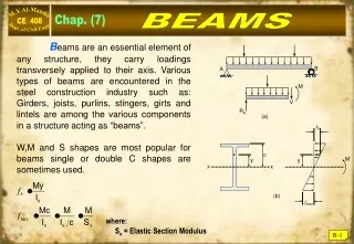
Download
1 / 9
90 likes | 232 Views
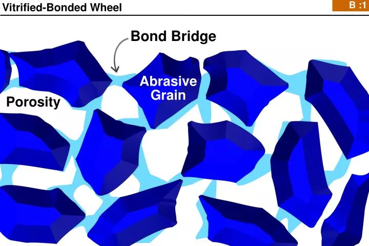
B : 1. Bond Bridge. Abrasive Grain. Porosity. Vitrified-Bonded Wheel. B : 2. quick-release grit region. middle-of-the-road region. stubborn-grit region. Bond refuses to release dull grits causing higher grinding power but a better surface finish due to the dull grits.

E N D
B :1 Bond Bridge Abrasive Grain Porosity Vitrified-Bonded Wheel
B :2 quick-release grit region middle-of-the-road region stubborn-grit region Bond refuses to release dull grits causing higher grinding power but a better surface finish due to the dull grits. Grits break out of bond material early. Keeps wheel sharp but gives poorer surface finish 1.4 μm 7 kW Surface Finish, Ra Grinding Power 1.2 μm 6 kW 5 kW 1.0 μm 4 kW 0.8 μm 3 kW 0.6 μm 2 kW 0.4 μm 1 kW 0.2 μm 0 kW 0.0 μm H I J K Wheel Grade Power in kW, General Surface Finish Data taken from Peters, Snoeys & Decneut, The proper selection of grinding conditions in cylindrical plunge grinding, Proceedings of the 16th International Machine Tool Design & Research Conference, MacMillan Press. Power normalized from Specific energy, grade approximation taken from The Shaw Hardness Method, Shaw, Principles of Abrasive Processing, 1996, eq. 5.13, Figure 121.
B :3 Making a grinding wheel is a bit like baking a cake. Consistency? Yes Logic behind the recipe? Well…. sort of. Sometimes. . .
B :4 How Are Grinding Forces Measured? FN: Normal Force FT: Tangential Force FN FT A dynamometer measures forces in three directions specimen specimen holder dynamometer Table velocity Source: J. Badger, Ph.D. Thesis, Trinity College, Dublin.
B :5 Forces vs. Time 40 I 35 K As the amount of wear flat area increases, the relative amount of rubbing and plowing will increase. Consequently, normal and tangential forces will increase. Notice that normal forces increase at a higher rate than tangential forces. 30 25 Normal Force (lbs) 20 Normal Force 15 G 10 5 0 10 K I Tangential Force (lbs) 5 G Tangential Force 0 0 20 40 60 80 100 Passes Kannappan, S. and S Malkin, “Effects of Grain Size and Operating Parameters on the Mechanics ofGrinding,” page 834, figure 4
C :6 Material Removal Rate (MRR) – Q Material Removal Rate (MRR) mm3 depth of cut in mm width of cut in mm feedrate in mm/s = × × s Material Removal Rate (MRR) width of cut in inches in3 depth of cut in inches feedrate in inches/min × = min × width of cut in mm depth of cut in mm feedrate in mm/s
F :7 But that’s not what happened. The post-grinding run-out profile actually looked like this, in green. 0.010 mm After Dressing After Grinding One grit diameter 0.250 mm 64 grit diameters 16 mm From the paper “Loading in Grinding: Chemical Reactions in Steels and Stainless Steels” by Badger, Murphy and O’Donnell, 2010 ISAAT Conference, Taiwan. 0.010 mm
G :8 What’s the Root Cause of Residual Stress? 6) Therefore, the hot material will be under compressive stress (as it wants to be larger than it is allowed to be) Compressive stress strain Tensile stress
H :9 Overview of dressing tools Single-Point Blade & Blade Fliesen Cluster Diamond Roll Rotary PCD Form Roll Form Roll Disk