Download
1 / 2
20 likes | 161 Views
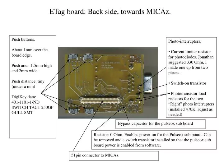
ETag board: Back side, towards MICAz. Push buttons. About 1mm over the board edge. Push area: 1.5mm high and 2mm wide. Push distance: tiny (under a mm) DigiKey data: 401-1101-1-ND SWITCH TACT 250GF GULL SMT. Photo-interrupters.

E N D
ETag board: Back side, towards MICAz. Push buttons. About 1mm over the board edge. Push area: 1.5mm high and 2mm wide. Push distance: tiny (under a mm) DigiKey data: 401-1101-1-ND SWITCH TACT 250GF GULL SMT • Photo-interrupters. • Current limiter resistor for photodiodes. Jonathan suggested 330 Ohm, I made one up from two pieces. • Switch-on transistor • Phototransistor load resistors for the two “Right” photo interrupters (installed 470K, adjust as needed) Bypass capacitor for the pulseox sub board Resistor: 0 Ohm. Enables power-on for the Pulseox sub board. Can be removed and a switch transistor installed so that the pulseox sub board power is enabled from software. 51pin connector to MICAz.
ETag board: Back side, towards MICAz. Place for LCD contrast potentiometer (not a user control, but just for adjustments) Connectors to the Pulseox sub board Two photo interrupters: TR and BR (top-right and bottom-right) Pulseox sensor / RS232 serial connector LCD (version 1b board does not support LCD, version 1c does). Two photo interrupters: TL and BL (top-left and bottom-left) LEDs LED switch components Photo transistor load resistors for the two “Left” photo interrupters (installed 470K, adjust as needed) RS232 level conversion circuit, not populated (alternative option to the Pulseox sub board feature)