Download
1 / 40
710 likes | 1.6k Views
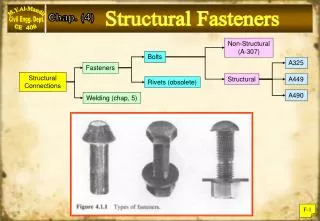
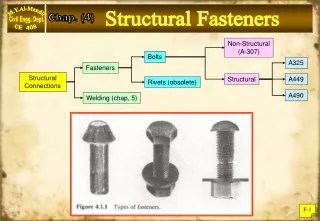
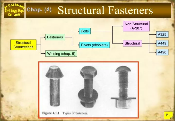
Structural Fasteners. Chap. (4). Non-Structural (A-307). Bolts. A325. Fasteners. Structural Connections. Structural. A449. Rivets (obsolete). A490. Welding (chap, 5). F-1. Shank. Threaded Section. Bolt Head. Bolt Designation:. F-2. Types of Bolted Connection.

E N D
Structural Fasteners Chap. (4) Non-Structural (A-307) Bolts A325 Fasteners Structural Connections Structural A449 Rivets (obsolete) A490 Welding (chap, 5) F-1
Shank Threaded Section Bolt Head Bolt Designation: F-2
Types of Bolted Connection The AISC specifications recognize two types of high-strength bolted connection:- A) Bearing Type Connection:- Where connected parts are allowed to bear directly on the bolt shank. Hence both shear strength and bearing strength need to be checked. B) Slip-Critical Type Connection (formerly known as friction-type connection):- Where connected parts are not allowed to slip, and shear forces are transmitted by friction forces rather than direct shear. This connection requires high pre-tensioning force of bolts upto their “proof load” which equals 70% of tensile strength. F-3
Proof Load of Bolts in Slip-Critical Connections When slip resistance is required, the pre-tensioning of bolts should as high as their “Proof Load”, which is equivalent to the yielding stress of the bolts material as obtaining by the 0.2% “offset method” or the 0.5% “extension method”. The proof load stress is a minimum of 70% and 80% of the minimum tensile strength of A-325 bolts, and the A-490 bolts respectively. The proof load can be achieved by using the turn-of-nut method, which is ½ turn of nut from the “snug-fit” position. Otherwise a “calibrated wrench” must be used to achieve the proof load for bolts. F-4
(70 % Fu) (70 % Fu) (80 % Fu) Properties of Bolts F-5
Butt Joint (double shear) Lap Joint (single shear) (a) Shear Connections W section Structural tee P P “Thread outside” (X) General Types of Bolted Connections The most typical types of bolted connections are shown below:- (d) Combined shear and tension connections (b) Eccentric shear Connection. (c) Tension Connections P In shear connection, threads could be:- A) In the shearing plane (N), or B) Outside the shearing plane (X). P “Thread inside” (N) F-6
Nominal Strength of Fasteners There are several “limit-states” or failure modes that may control the strength of a bolted connection. As can be seen from the above figure, three failure modes (b, d & g) are relevant to the connected plates and not relevant to the fasteners. F-7
Tensile Strength of Fasteners The nominal tensile strength of a bolt (Rn) can be found as: Where Fub = Tensile strength of the bolt material. An = Bolt net area through threaded zone*. This net area 0.75 to 0.79 of the bolt gross area Ab (area of the shank). Thus: Thread cross section area * Where, db = dia. of bolt (shank) n = number of threads per inch. Note: Tensile strength values Fub are given in LRFD table J3.2 page (16.1)-104. F-8
The nominal-shear strength for one fastener (Rn) will be Rn = m Abu Where, = (1) for single shear m = number of shear planes = (2) for double shear Ab = Bolt gross area. u = Ultimate shear strength for the bolt material, found experimentally to be around (0.62 Fub) of the ultimate tensile strength (Fub). Thus: Rn = m Ab (0.62 Fub) Shear Strength of Fasteners F-9
Bearing Strength of Fasteners The bearing failure near the edge of the plate is related to the shear failure (tear-out) as shown in figure 4.6.4 b & d (page F-7). Assuming angle () 0 as shown in figure 4.6.5 below: Where up = Shear strength of plate material = 0.62 Fu Fu = Ultimate tensile strength of plate material. Le = Distance from center of last bolt to the edge of plate along direction of force. d = Nominal Bolt diameter. F-10
Thus: Since LRFD recommends spacing of bolts in the direction of force to be (2.67 d) – [see LRFD J – 3.3]. Consider (Le 2.67 d) above: * Rn = 2.4 Fu dt or * Rn = 3.0 Fu dt (When deformation of the hole at service load is a design consideration). (Eq J3-6a) (When deformation of the hole at service load is not a design consideration). (Eq J3-6b) The lower resistance value guarantees that no tear-out due to bearing shall occur below this (Rn) value, and no Deformation at the hole shall occur at service load level. (AISC J3-10 Page16.1-111) F-11
In general: nRn Σ iQi Where, Rn = Nominal resistance (strength) n = Strength reduction factor (resistance factor) iQi = Factored load on structure (ASCE – 7) for a single bolt : Rn Pu Where, u = 0.75 for fracture in tension, shear or bearing. Rn = Nominal strength of one fastener Pu = factored load on one fastener The strength of a fastener is based on: 1- Tension capacity 2- Shear capacity 3- Bearing capacity (1) Threads are included in shear plane (N) (2) Threads are excluded from shear plane (X) Load & Resistance Factor Design for Fasteners F-12
= Tensile strength of bolt material (120 ksi for A – 325 Bolts & 150 ksi for A – 490 Bolts). Ab = Gross area of the bolt (Shank section). Design for Tension Strength Reference is made to (LRFD) – J 3.6), and page (F-8): or Where = 0.75 as stipulated in AISC J3.6 (page 16.1-108) F-13
Design for Shear Strength (LRFD) A – No threads in shear plane (X):- Rn = 0.75 (Rn) (AISC J3-6) Rn = 0.62m AbFub (page F-9) For long Connections (upto 50 inch long), a 20% reduction is needed (strength of long connection < Σ of strength of individual bolts). Thus:- Rn = (Reduction due connection length)(0.62 Fub)m Ab = 0.8 x 0.62 Fub . m Ab = 0.5 Fub m Ab Rn = (0.75)(0.5) Fub m Ab Where, Fub = Ultimate strength of bolt material: 120 ksi for A – 325 ; 150 ksi for A – 490 m = 1 for single shear , 2 for double shear Ab = Area of the shank portion of bolt (See LRFD J 3.6 & table J 3.2) F-14
Design for Shear Strength (LRFD) B - Threads in Shear Plane (N):- The area of the threaded section of the bolt is about 75% of the gross area at the shank section, Thus: Rn = [Reduction for length] (0.62 Fub) m (0.75 Ab) = (0.8)(0.62 Fub) m (0.75 Ab) = 0.37 Fub m Ab (0.40 Fub) m Ab Hence: Rn = 0.75 (0.4 Fub) m Ab (see Table J-3.2) F-15
Design for Bearing Strength Nominal bearing strength (Rn) was developed earlier (page F-11). However LRFD-J3.10 further reduces (Rn) in order to prevent bolt elongations exceeding 0.25 in. Hence several categories are presented here below: 1: Deformation Limit State (Standard Holes):- Where Le 1.5 d and c/c spacing 3d, and there are two or more bolts: Rn = (2.4 dt Fu) …………..(Equ.. J3-6a) = 0.75 d = Nominal diameter of bolt at shank section. t = Thickness of the least connected plate. Fu = Ultimate tensile strength of the connected plate. F-16
2: Deformation Limit State (Long-Slotted Holes): Same as previous conditions. Rn = (2.0 dt Fu)… (Equ. J2 6c) Where = 0.75 ......... (AISC - J3 – 10 Page 16-1-111) 3: Strength Limit State (hole elongation 0.25 in.): Rn = (3.0 dt Fu) ……. (Equ. J3 – 6b) See page (F-11) of these notes. F-17
A) Minimum Spacing Bolts along line of Force: 2.67 d s 3d (AISC J3.3) where, s = spacing of bolt along force line. d = diameter of bolts-shank section B) Minimum Edge Distance along Line of force: Normally min. edge distance (rolled edge) Normally min. edge distance (sheared edge) Where d = Nominal diameter of the bolt. (Reference table J3-4 page 16.1 – 107) Min. & Max. Edge Distances & Spacing for Bolts: F-18
C) Maximum spacing for Bolts: for Painted members: s 24t but 12 in. for unpainted members: s 14t but 7 in. t = thickness of the thinner connected plates. D) Maximum Edge Distance: max. edge distance = 12 t but ≤ 6“ ... (AISC J 3.5 Page 16.1 – 106) t = thickness of the thinner connected plates. Reference: AISC J 3.5. (AISC page 16.1 – 108) F-19
Design of Bolts in Tension Example F-1 Determine the required number of ¾ in. dia. A490 bolts for the connection below. Assuming DL = 14 kips, LL = 126 kips? Solution:- a) Calculate the factored load: Tu = 1.2 DL + 1.6 LL = 1.2 14 + 1.6 126 = 218 kips. b) Design strength Rn per bolt: Rn = 0.75 Fub (0.75 Ab) = 0.75 113 0.4418 (AISC Table J 3.2) = 37.3 kips. c) Number of bolts required: (say 6 bolts) use 6 – ¾ in A 490 bolts. F-20
Tension Member Bearing-Type Connection-LFRD Bearing Type Connections Example F-2 Compute the tensile factored load capacity for the bearing type connection shown below, Assume (A-572 Grade 50) steel plates, with (7/8”) diameter A-325 bolts in standard holes: A) Bolt threads are excluded from shear plane (X). B) Bolt threads are included from shear plane (N). Solution:- Check Plate Capacity: Tn = 0.90 50 3.75 = 169 kips. or Tn = 0.75 65 2.50 = 122 kips. (controls) F-21
A) Strength of A-325-X bolts: Shear: Rn = (0.5 Fub) m Ab = 0.75 0.5 120 1 0.6013 = 27.1 kips per bolt. Bearing: Since Le ≥ 1.5d and spacing S > 3d, the bearing strength of a bolt is: Rn = (2.4 Fu dt) = 0.75 2.4 65 0.875 0.625 = 64 kips per bolt. Thus shear controls, the capacity of the connection: Tn = 4 27.1 = 108 kips < 122 kips So, Connection capacity = 108 kips. F-22
B) Strength of A-325-N bolts: Shear: Rn = (0.4 Fub) m Ab = 0.75 0.4 120 1 0.6013 = 21.6 kips per bolt. No need to check bearing again, Since Shear will control: Tn = 4 21.6 = 86.4 kips Total Connection capacity = 86.4 kips F-23
Design of Bearing Type Connections Example F-3 Determine the number and spacing of (¾ in.) dia. (A-490-N) bolts required to develop the full strength of the A-572 Grade 65 plates shown below. Assume double rows of bolts with standard holes? Solution:- Consider middle plate: Ae = An = 1.59 sq. in. (well connected). max. An = 0.85 Ag = 0.85 6 0.375 = 1.91 sq. in. (check T-16 of these notes) Tn = Fy Ag = 0.90 65 6 0.375 = 132 kips. or Tn = Fu Ae = 0.75 80 1.59 = 96 kips. (controls) F-24
Bolt shear capacity for ¾ in. A-490-N bolt: Rn = (0.4 Fub) m Ab = 0.75 0.4 150 2 0.4418 = 39.8 kips per bolt. (controls) Bearing Strength on the 3/8 in. plate: Rn = (2.4 Fu dt) = 0.75 2.4 80 0.75 0.375 = 40.5 kips per bolt. Number of bolts = =2.4 bolts. Use 4-¾ in. (A-490-N) bolts. With: End distance must be at least and spacing of bolts F-25
Design the connection below to develop the full strength of double angles (back-to-back), using two lines of (¾ in.) dia. (A-325-N) bolts in the bearing type connection of 2Ls 6 4 (A-36) material ? + + Design of Bearing-Type Connections Example F-4 2Ls 6 x 4 x 3/8 Pu (A-36 Steel) Number of bolts To be determined. ½“ Gusset Plate ( ½“ Thick) – (A-36) F-26
Solution:- For a single angle: Ag = 3.61 sq. in. U = 0.80 (assuming 4 bolts or more in one row) Ae = U An = 0.80 2.95 = 2.36 sq. in. = 0.9 3.61 36 = 117 kips. Angle Capacity (Pu) = 0.75 2.36 58 = 102.7 kips. (controls) (Pu) for two angles = 205.4 kips. F-27
4” 2¼ 6” 2½ 1¼ 2 ¼ 2 ¼ 2 ¼ 1½ Design for Bolts Shearing capacity each bolt = Bearing capacity each bolt = 0.75 2.4 0.75 ½ 58 = 39.2 kips (Gusset plate more critical) Required No. of bolts Use 8 bolts (Four in line). Use spacing as shown below: Re-Check: from L data: F-28 Higher value of (U) is always on the safe side.
Slip-Critical Connections:- In slip-critical type connection (page F-3), plates are not allowed to slip against each other, hence there is no practical shearing or bearing contact between the bolts and the joining plates (or shapes). This necessities the need for high quality control over the bolt tension (proof load). The main performance criteria of the slip-critical type connection is that no slippage of the connected parts should occur at the service load level at the structure. However, to make the design of the slip-critical type connection compatible with the design of the bearing type connection, AISC stipulates the design of slip-critical connection at the factored load level of the connected elements, as follows:- F-29
Design of Slip-Critical Type Connection Rn = Du hsc Tb Ns (AISC J 3.8) (Page 16.1 – 109) where: • = 1.0 for connections which resist slip at the service load level. Rn = Nominal slip resistance of a (sc) bolt in kips. • = Friction coefficient for class A & B surfaces: = 0.35 for class (A) surface (clean mill scale). = 0.50 for class (B) surface (blast clean surface). Du = 1.13 a statistical factor related to bolt pretension. Hsc = Hole factor hsc =1.0 for standard holes. hsc = 0.85 for Oversized holes. hsc = 0.70 for long-slotted holes. Ns = Number of slip planes (1 or 2) as (m) before. Tb = Minimum fasteners tension in kips. (Table J3.1). F-30
6 x ½ 1.5” 3” Tu 1.5” 3” 1.5” 1.5” (a) Capacity of Slip-Critical Connection Example F -5 The connection shown below uses (¾ inch) A 325 SC bolts. No slippage is permitted. All connected members are (A-36) steel. Determine strength capacity of this connection (Tu) Solution :- Even the connection is specified as slip-critical connection, the direct shear and bearing capacity must be checked (in the event of accidental slippage). F-31
1) Shear capacity of bolts (A-325 N): = 15.90 kips per bolt. Tu for four bolts = 15.90 4 = 63.6 kips. 2) Bearing Capacity of (A325N) bolts. Since the gusset plate is thinner (3/8” < ½”), It will control bearing : Rn = (2.4 d t Fu) = 29.36 kips • Bearing for four bolts : Rn = 4x29.36 = 117.45 kits F-32
Slip-Critical Connection:- • Rn = Du hsc Tb Ns • where, • = 1.0 • = 0.35 assume class (A) surface. • Du = 1.13 • hsc = 1.0 standard holes • Tb = 28 kips (Table J 3.1) • (Table 16.1 – 103) • Ns 1 slip plane. • Rn = 1 0.35 1.13 1 28 1 = 11.1 kips per bolt • For four bolts Tu = 4 11.1 = 44.4 kips. F-33
0.9 Fy Ag Rn= 0.75 Fu Ae (controls) 4) Tension on the plate :- Maximum Capacity Tu = 44.4 kips. F-34
Gusset plate Angle (A 572 – Gr 50) D = 8 kips L = 22 kips A 325 SC bolts A572 Grade 50 steel Design of Slip-Critical Connection Example F-6: A 13-foot-long tension member and its connection must be designed for a service dead load of 8 kips and a service live load of 22 kips. No slip of the connection is permitted. The connection will be to a 3/8-inch-thick gusset plate, as shown. Use a single angle for the tension member. Use A325 SC bolts and A572 Grade 50 steel for both the tension member and the gusset plate. F-35
Solution: The factored load to be resisted is Pu = 1.2D + 1.6L = 1.2(8) + 1.6(22) = 44.8 kips Because the bolt size and layout will affect the net area of the tension member, we will begin with selection of the bolts. The strategy will be to select a bolt size for trial, determine the number required, and then try a different size if the number is too large or too small. Bolt diameter typically range from ½ inch to 1½ inches in 1/8-inch increments. Try 5/8 inch bolts. The nominal bolt area is The shear strength is Rn = FvAb = 0.75(48)(0.3068) = 11.04 kips/bolt (assuming that the threads are in the shear plane) • Rn = Du hsc Tb Ns = 1 0.35 1.13 1 19 1 = 7.5 kips (controls) No slip is permitted, so this connection is slip-critical. We will assume class (A) surfaces, and for a 5/8-inch-diameter A325 SC bolt, the minimum tension is Tb = 19 kips (from AISC Table J3.1). F-36
Say 6 bolts ;This can be achieved in two rows, which requires long leg for the angle, or select a larger size bolt to have less number of bolts, in order to fit in one line. Try (¾ inch) diameter bolts. (assuming thread in shear plane after slip have occurred). • The Slip-Critical bolt capacity : • Rn = 1 0.35 1.13 1 28 1 = 11.07 kips. (controls) F-37
2½” 2½”2½” 1½” 1½” Select four bolts of (¾ in.) diameter (A-325-SC) Minimum spacing 3 d = 2¼ in. say (2½ in.) Minimum Edge distance = 1.5 in (assume sheared edge). Check Tension on Member : and the required effective net area is F-38
For the layout shown in Figure above, with four bolts in the line of force, the value of U from the AISC table – D3.1 (page 16.1-29) is 0.80. (Once a member has been selected, U can be computed with AISC. Therefore Assume t = ¼ in thick, (Ag)2 = 1.35 in.2 (controls) F-39
Use an with Long leg connected. Use A325-SC bolts as shown. Selection of Section: 2½” Ag = 1.44 in2 > 1.35 in2 (OK) rmin = rz = 0.544 in. > 0.52 in. (OK) 3½” Our selected Ag = 1.44 in2 is greater then (Ag)2 Then OK. F-40