Download
1 / 75
970 likes | 1.22k Views
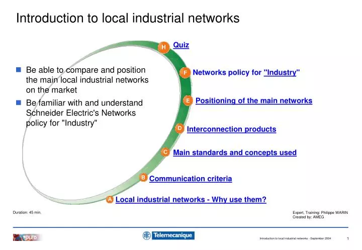
Introduction to local industrial networks. Quiz. H. Be able to compare and position the main local industrial networks on the market Be familiar with and understand Schneider Electric's Networks policy for "Industry". Networks policy for "Industry ". F. Positioning of the main networks. E.

E N D
Introduction to local industrial networks Quiz H • Be able to compare and position the main local industrial networks on the market • Be familiar with and understand Schneider Electric's Networks policy for "Industry" Networks policy for "Industry" F Positioning of the main networks E Interconnection products D Main standards and concepts used C Communication criteria B Local industrial networks - Why use them? A Duration: 45 min. Expert, Training: Philippe WARIN Created by: AMEG
WHY USE THEM? Quiz H Networks policy for "Industry" F Positioning of the main networks E Interconnection products D Main standards and concepts used C Communication criteria B Local industrial networks - Why use them? Local industrial networks - Why use them? A
Digital data 1 0 Serial link - what is a local industrial network?
- lower installation costs Networked Not networked
In the event of interference, the message can be repeated - less sensitivity to electromagnetic interference Digital speed command 0 - 32767 Analogue speed command 0-10 V No interference on the value received Interference on the value received Networked Not networked
Configuration of local reflex actions Addition of an optional cardfor remote automation - possibility of intelligence distribution
Motor overload fault Generic fault - accurate diagnostics in the event of a fault Networked Not networked
OOS module - easier replacement of defective equipment
COMMUNICATION CRITERIA Quiz H Networks policy for "Industry" F Positioning of the main networks E Interconnection products D Main standards and concepts used C Communication criteria Communication criteria B Local industrial networks - Why use them? A
Who am I speaking to? Number of correspondents? When can I speak? One or more speakers? Do I have to send information at regular intervals? Can I be replaced? What distance? What facility should I use? Maximum message size? Have you understood? OSI Model: classification and organisation Which language? Is it urgent? - to communicate...
Division into homogeneous and ordered subsets - the OSI model from ISO • OSI model: Open System Interconnection Seven-layer architecture • ISO: International Standards Organization
- description of the OSI model PROFILE Standardisation of functions for interchangeability purposes APPLICATION LAYER Grammar - Semantics 7 PRESENTATION LAYER Format conversion 6 SESSION LAYER Organisation and synchronisation of exchanges 5 TRANSPORT LAYER End-to-end routing control 4 NETWORK LAYER Data routing 3 Link control LINK LAYER 2 Medium access control PHYSICAL LAYER 1 Hardware
- local industrial network criteria PROFILE Interchangeability: EDS, GSD files? Language: Modbus, FMS? APPLICATION LAYER Process data: Client-server, producer-consumer content, periodicity? 7 Service data: Accessible variables, max. size? Medium access: master-slave, token ring, random access? Addressing: address 1, 5, general distribution? 2 LINK LAYER Transmission control: parity check, CRC, delimiters? Flow control: NACK, XON-XOFF, inhibit time? 1 PHYSICAL LAYER Medium: twisted pair, coaxial cable, optical fibre? Topology: bus, star, tree, grid? Max. no. of devices: 2, 31, 64, 128? Max. distance between devices:100 m, 1 km, 15 km?
MAIN STANDARDS AND CONCEPTS USED Quiz H Networks policy for "Industry" F Positioning of the main networks E Interconnection products D Main standards and concepts used Main standards and concepts used C Communication criteria B Local industrial networks - Why use them? A
LAYER 1: PHYSICAL The main media used Standard twisted pairs: RS232, RS422, RS485 The various topologies
Low Cost High Physical layer 1 - the main media used • The choice of MEDIA affects the: • speed • distance • electromagnetic immunity • Most commonly used media: • pair(s) of shielded twisted wires • coaxial cables • optical fibre:
Physical layer 1 - standard twisted pairs • RS232: • Point-to-point link via 25-pin or 9-pin SUB-D connector. • Distance < 15 m, speed < 20 Kbps • RS422: • Full-duplex (simultaneous bidirectional) multi-drop bus on 4 wires. • Good immunity to interference, maximum distance 1000 m at100 Kbps. • 2 transmission wires, 2 reception wires • RS485: • Half-duplex (alternate bidirectional) multi-drop bus on 2 wires. • Same electrical characteristics as RS422A but on 2 wires.
Chaining Bypass Line termination resistors Physical layer 1 - the various topologies RING POINT-TO-POINT Example: Used by Interbus Example: PC - PLC console connector link STAR GRID Example: Internet network via routers Example: PCs connected over Ethernet via a HUB TREE BUS Example: Intranet network via hubs and switches Example: CANopen, DeviceNet, Profibus-DP, FIPIO, Modbus RS485
Transparent for the user, with the exception of addressing LAYER 2: LINK Main medium access methods Master - Slave Token Ring Random access Addressing Transmission quality control Character level parity check Message validity check using a control word Message format check using delimiters Flow control
Master - Slave Token Ring Random access Destructive collision: CSMA-CD Link layer 2 - medium access When can I speak? When the master invites me to speak When it’s my turn When no-one else is speaking Non-destructive collision: CSMA-CA
Polling Do you have anything to say? Used by Asi, FIPIO, Modbus, Profibus-DP and Uni-Telway Nothing to declare! Response Can be used on CANopen and DeviceNet (by configuration) Link layer 2 - the Master-Slave system • The master grants access to the medium • The slave can access the medium after being polled by the master Master Slave
Used by Modbus Plus Link layer 2 - Token Ring • Ring: the members of a ring are authorised to send data upon receipt of the token. • Token: a group of bits passed from one node to another in ascending order of address. Address 2 Address 1 Address 3 Address 4
Data can be transmitted as soon as a silence is detected. Link layer 2 - random access • Each device "listens" whilst it transmits • If the data received is different from the data sent, a collision occurs • 2 types of collision: destructive non-destructive
Stop Principle used by Ethernet and known as CSMA-CD CSMA-CD = Carrier Sense Multiple Access - Collision Detection Link layer 2 - random access with destructive collisions Step-by-step operation in the event of a collision: • any messages in the course of transmission are stopped • a scrambling frame is sent: the frame is lost • a random wait time is observed • the message is resent
Dominant Recessive Stop Principle used by CANopen and DeviceNet and known as CSMA-CA CSMA-CA = Carrier Sense Multiple Access - Collision Avoidance Link layer 2 - random access with non-destructive collisions The message remains valid, due to a system of dominant and recessive bits • the device with the lower priority stops its transmission (recessive bit) • the device with the higher priority completes its transmission • the device with the lower priority tries to send its message again as soon as the medium is free
Advantys FTB interface x10 x1 Address 77 Link layer 2 - addressing Who am I speaking to? Lucy Fred A group
Use of reserved address values: 0, 255. Cannot be configured on the devices Link layer 2 - example of addressing Example using a Modbus frame EOF SOF Address Function Data Checksum Address = 77 If a message is intended for all the devices: General distribution or Broadcasting
Welding station Character level parity check Message validity check using a control word Message format check using delimiters Link layer 2 - transmission quality control Have you understood? Got it! I didn't hear the end of the sentence
Address Start Bit 7 Bit 6 Bit 5 Bit 4 Bit 3 Bit 2 Bit 1 Bit 0 Parity Start Address = 77 includes 4 bits at 1 1 0 1 0 0 1 1 0 1 Parity 1 1 0 Even parity Odd parity Even number of bits at 1 Odd number of bits at 1 Link layer 2 - character level parity check Example using a Modbus frame SOF Function Data Control word EOF Address
Field containing a value calculated from a block of bits and used to check the validity of the whole message. Examples : Checksum CRC = Cyclic Redundancy Check LRC = Longitudinal Redundancy Check Link layer 2 - message validity check using a control word Example using a Modbus frame SOF Address Function Data Control word EOF
Standard information inserted in each message to delimit different fields: start, end, etc. Additional transmission quality checks Link layer 2 - message format check using delimiters Example using a Modbus frame SOF Address Function Data Checksum EOF
NACK = Not acknowledged XON-XOFF Inhibit Time Link layer 2 - flow control Wait, let me finish!!!
LAYER 7: APPLICATION Application layer 7 Messaging Client-Server system Producer-Consumer system Data Types Process data Service data Traffic types Cyclic exchanges Acyclic exchanges
Messaging systems: Modbus UNI-TE FMS Messaging: Client - Server Application layer 7 - messaging Which language shall we use? French? English? Italian?
Request What is the engine speed? Request Can you put it into reverse? Request Would you bring the bill please? It’s in reverse Response Straight away, Madame Used by Modbus, UNI-TE, FMS, etc. Response 1000 rpm Response Application layer 7 - Client-Server system The CLIENT is an entity requesting a service The SERVER is the entity that responds to a request from a client Server Client
The PRODUCER is a single entity that produces information Maybe I'll go to the cinema I am changing my speed to 1200 rpm Speed = 1200 rpm It's 13:51 It's time for my match I display the speed Consumer 1 Consumer 1 Producer Producer Consumer 2 Consumer 2 Used by CANopen and DeviceNet Application layer 7 - Producer-Consumer system The CONSUMERis an entity that uses it (several entities can use the same information).
Low volume of data Large volume of data Sent at startup or in the event of a problem No time constraint Quickly refreshed at regular intervals or on change of state Application layer 7 - data types Process data Service data Monitoring - Control Configuration - Settings - Diagnostics
At startup, the configuration and settings data is automatically transmitted Refreshed automatically 2 word tables: inputs and outputs If required, activation via programming, in the case of settings or diagnostics data Application layer 7 - traffic types Cyclic exchanges Acyclic exchanges Used for process data Used for service data
PROFILE Profile Open system Profile EDS files
An open system= interoperable and interchangeable components Achieved through strictadherence to protocol specifications. Achieved through strict adherence to profile specifications. Profile - open system Interoperability=ability of devices to communicate intelligibly with one another Interchangeability= ability to replace one device with another
Profile = is a standardised way of describing the functions of a device An EDS file is an example Profile - device profile Can you take my place? Dark hair, brown eyes, 25 years old 5' 6" 9 stone 4 lb Blond hair, blue eyes, 15 years old 5' 3" 8 stone Brown hair, green eyes 8 years old 4' 3" 5 stone
Configuration Data EDS = Electronic Data Sheet ---> Strict syntax Applications Objects Network On floppy disk or CD-ROM - Downloadable Configuration Tool Device Used by network configuration software Electronic Data Sheet Device information For Profibus-DP: EDS = GSD Profile - EDS file
INTERCONNECTION PRODUCTS Quiz H Networks policy for "Industry" F Positioning of the main networks E Interconnection products Interconnection products D Main standards and concepts used C Communication criteria B Local industrial networks - Why use them? A
Length - Number of devices Physical layer 1 Link layer 2 Network layer 3 Physical medium adaptation Length - Number of devices - Collisions Lower layer adaptation Connection between networks of the same type Application layer 7 Connection between networks of different types - improvement or adaptation of network specifications Repeater Hub Transceiver Switch Bridge Router Gateway
Example: ASi repeater Reference: XZMA1 Connected to a flat cable by means of a vampire connector - repeater Repeater Can be used to increase the length and the number of devices that can be connected by adding a new segment Signal amplifier 1 1 Segment 1 Segment 2
Example: 4-port 10 Mbps Ethernet hub RJ45 Reference: 499NEH10410 4 x 10baseT - hub Hub Can be used to increase the length and the number of devices by adding several segments. 1 device per segment. Star topology. It amplifies a signal received on a port and sends it to all the other ports 1 1 1 1
Example: Ethernet twisted pair - fibre optic transceiver 100 Mbps Reference: 499NTR10100 Conversion 100baseTX (RJ45) - 100baseFX (SC) - transceiver Transceiver Can be used to adapt different types of physical media. Signal converter. 1 1 Segment 1 Segment 2
Example: 8-port 10/100 Mbps Ethernet switch Reference: 499NES18100 8 x 10baseT / 100baseTX (RJ45) - switch Switch Can be used to increase the length and the number of devices by adding several segments. Star topology. When a message is received, the receiver's address is analysed and sent to the corresponding port. 2 2 2 2 1 1 1 1
Example: Modbus Ethernet TCP-IP / Modbus serial link bridge Reference: 174CEV30010 Ethernet interface: 1 x 10baseT = RJ45 Modbus interface: RS232 or RS485 on RJ45 or screw terminals - bridge Bridge 2 2 Can be used to connect two networks using the same application layer but different lower layers 1 1 Network 1 Network 2
Example: Allied Data Ethernet router - router Router Can be used to route information between networks using the same application layer Mainly used by the Internet via IP addresses 3 3 2 2 1 1 Network 1 Network 2