Download
1 / 22
220 likes | 330 Views
Update on Analysis of FNAL TB09. Jianchun Wang for the group Syracuse Univesity Jan 29 th ,2010. Testbeam Team at FNAL.

E N D
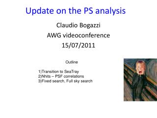
Update on Analysis of FNAL TB09 JianchunWang for the group Syracuse Univesity Jan 29th ,2010
Testbeam Team at FNAL • June 2008: Tony Affolder, Marina Artuso, Alessandra Borgia, Lars Eklund, Karol Hennessy, Gwen Lefeuvre, Ray Mountain, AbdiNoor, Chris Parkes, Sheldon Stone, Jianchun Wang • April 2009: Marina Artuso, Alessandra Borgia, TorkjellHuse, David Hutchcroft, Ray Mountain, Jianchun Wang • Pixel system: David Christian (FNAL), Bruce Knapp (Nevis Lab), Jianchun Wang • More from remote Jianchun Wang
Introduction Y Z X • The system and analysis procedure: • Independent DAQ systems for Pixel & VELO, sharing trigger signals. Events are matched offline. • Tracks are reconstructed from pixel hits and fit to straight lines, multiple scattering is treated separately. Pixel stations/modules are aligned within its own system. • Velosensors are aligned with respect to the pixel tracks. Tracks, corresponding Velo event IDs and alignment parameters are saved in tracking data files. • Pixel tracking data are fed to Vetra for VELO analysis. • Non-irradiated N-type R sensor (R/f pair) • Charge sharing & resolution for different pitches and track angles. • Presented at 10/19/09 TREC meeting. Some plots are included here for comparison. • Differentially irradiated N-type & P-type R sensors (RR pair) • Most probable charge vs irradiation particle fluence ( presented at 12/07/09 VELO meeting), some are updated here. • Most probable charge for different bias HVs. • Detection efficiency and resolution. VELO Scint Pixel Pixel Pixel Just a reminder 120 GeV proton beam YX Y YX RR(F) Jianchun Wang
Basic on Charge Distributions • The FE electronics were under-powered, resulting in low gain. Most probable charge ~16 ADC instead of ~40. • Constant thresholds (seed=3.6, inclusion=1.8) are used (noise ~ 0.9 ADC counts). Thresholds are low enough to study irradiated sensors. • Gain differences are partially corrected using header heights. • Only hits that match with pixel tracks are looked at, to reduce the influence from uncertainty of noise hits. • Charge distributions are fit to Landau convoluted with Gaussian. The width of Gaussian is fixed to an average value so as to reduce the uncertainty on Landau MP. • In some cases there are shoulders/tails on low side that were not well understood. Fits are at peak areas. Fit range affects MP obtained from fit. MP represents, but not completely, the charge collection efficiency. Charge (ADC counts) Jianchun Wang
Sensor Charge Collection Tracks at 0-8 degrees, detector biased at 500 V. Hit map determined by pixel tracks that matche with VELO hits. X (mm) X (mm) ? N-type P-type ? = – Y = + Y Jianchun Wang
MP Charge At Different HVs Bias Voltage (V) 500 400 300200 100 50 N-type P-type No HV scanned for middle part due to tight schedule. It is difficult to extract correct MP when MP is close to threshold. Jianchun Wang
Comparing Different Electronics Settings optimized for sensors after irradiation. N-type Kazu setting P-type Kazu setting biased at 500 V Optimized for current running in the pit. P-type Chris setting N-type Chris setting Jianchun Wang
Detection Efficiency • Due to the trigger scheme and different DAQ clock frequencies for the two systems, tracks seen by pixel and VELO are not necessarily the same. • Pixel tracks are matched with hits from one sensor (± 200 mm) to ensure this is a real track and seen by VELO. • We then look at the other sensor to see if there is hit that matches the track. The detection efficiencies are thus determined. • Beam profiles are not guaranteed to be the same for different conditions so the weight of dead areas changes for different condition runs. • A dead chip and few dead strips and certain border areas are removed. • In this way, the detection efficiencies reflect more precisely the effect of irradiation fluencesand/or bias voltages. Jianchun Wang
Cleanup of Dead Strip & Borders hit position expectation that are unmatched N-sensor N-sensor ! Remove 6 bad strips & borders Y (mm) Y (mm) P-sensor P-sensor Remove 4 bad strips & borders ! X (mm) X (mm) Jianchun Wang
Detection Efficiency Normal incident tracks Biased at 500 V P-type Kazu setting N-type Kazu setting Not from 0 Jianchun Wang
Detection Efficiency Bias Voltage (V) 500 400 300200 100 50 All angles N-type Kazu setting P-type Kazu setting Jianchun Wang
Detection Efficiency All angles N-type Chris setting P-type Chris setting ? Jianchun Wang
For Resolution Study Pitch ( mm ) Track Effective Angle (degree) • Select regions Y< –16 mm & Y > 16 mm. • Angles: 0-2, 2-4, 6-8 degrees • Pitches: 64-70, 70-80, 80-90, 90-100 mm Y (mm) Jianchun Wang
Resolution vs Pitch N-type 0-2 degree R of R/f pair (Chris, 0 degree) R of R/f pair Fully irradiated (Chris) Normal Incidence (0.5) Fully irradiated (Kazu) Non-irradiated (Kazu) P-type 0-2 degree Fully irradiated (Kazu) Non-irradiated (Chris) Non-irradiated (Kazu) • Resolutions are obtained through Gaussian fit to residual distributions, not just RMS due to bkg hits. • Tracking errors are removed. Error not fully estimated Jianchun Wang
Charge Sharing vs Pitch Non-irradiated (Kazu) Fully irradiated (Kazu) Angle ( ) -0.5 – 0.5 2.5 – 3.5 6.5 – 7.5 10.5 – 11.5 R of R/f pair Fully irradiated (Chris) R of R/f pair (Chris, 0 degree) N-type 0-2 degree Non-irradiated (Kazu) Non-irradiated (Chris) P-type 0-2 degree Fully irradiated (Kazu) Error not estimated Jianchun Wang
Resolution vs Pitch N-type R of R/f pair • Irradiated • Fully • None • Angle (degree) • 0-2 • 2-4 • 6-8 Angle ( ) - 0.5 – 0.5 2.5 – 3.5 6.5 – 7.5 10.5 – 11.5 P-type Error not fully estimated Jianchun Wang
Center of Residual vs HV 64 – 70 mm N-type fully-irradiated 6-8 degree tracks 70 – 80 mm 80-90 mm 90 – 100 mm Naïve interpretation Max difference ~150tan(8) = 21 mm Jianchun Wang
Center of Residual vs HV P-type non-irradiated 6-8 degree tracks 64 – 70 mm 70 – 80 mm Full depletion voltage ~ 110 V 90 – 100 mm 80-90 mm Jianchun Wang
Summary • Data on irradiated sensors are analyzed. • Most probable charge, detection efficiency, charge sharing and resolution are measured for different pitch, HV and irradiation dose. • Paper draft is on the way. • More ideas may come up while producing paper draft. • Some systematic errors already added, more will be included. • Suggests and contributions are welcome. Jianchun Wang
Comparison Between N- and P-type Sensor P-type N-type Jianchun Wang
More on N-type Sensor N-type sensor Artificial parameter from MP so that the shape looks more like the irradiation profile Slopes in the transition region exhibit small discrepancy. Jianchun Wang
MP vs HV P-type N-type Fit with a naïve function Non-irradiated Non-irradiated Vdep = 117±7 V From non-irradiated irradiated irradiated Vdep = 1218±96 V Vdep = 771±43 V Jianchun Wang