Download
1 / 66
690 likes | 788 Views
The Physical Layer. Chapter 2. The Theoretical Basis for Data Communication. Fourier Analysis Bandwidth-Limited Signals Maximum Data Rate of a Channel. Bandwidth-Limited Signals. A binary signal and its root-mean-square Fourier amplitudes.

E N D
The Physical Layer Chapter 2
The Theoretical Basis for Data Communication • Fourier Analysis • Bandwidth-Limited Signals • Maximum Data Rate of a Channel
Bandwidth-Limited Signals A binary signal and its root-mean-square Fourier amplitudes. (b) – (c) Successive approximations to the original signal.
Bandwidth-Limited Signals (2) (d) – (e) Successive approximations to the original signal.
Bandwidth-Limited Signals (3) Relation between data rate and harmonics.
Bandwidth • The range of frequencies transmitted without being strongly attenuated is called the bandwidth. • The bandwidth is a physical property of the transmission medium and usually depends on the construction, thickness, and length of the medium. • In some cases a filter is introduced into the circuit to limit the amount of bandwidth available to each customer. • For example, a telephone wire may have a bandwidth of 1 MHz for short distances, but telephone companies add a filter restricting each customer to about 3100 Hz. This bandwidth is adequate for intelligible speech and improves system-wide efficiency by limiting resource usage by customers.
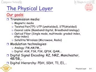
Guided Transmission Data • Magnetic Media • Twisted Pair • Coaxial Cable • Fiber Optics
Twisted Pair (a) Category 3 UTP. (b) Category 5 UTP.
Coaxial Cable A coaxial cable.
Fiber Optics (a) Three examples of a light ray from inside a silica fiber impinging on the air/silica boundary at different angles. (b) Light trapped by total internal reflection.
Transmission of Light through Fiber Attenuation of light through fiber in the infrared region.
Fiber Cables (a) Side view of a single fiber. (b) End view of a sheath with three fibers.
Fiber Cables (2) A comparison of semiconductor diodes and LEDs as light sources.
Fiber Optic Networks A fiber optic ring with active repeaters.
Fiber Optic Networks (2) A passive star connection in a fiber optics network.
Cont.. • A ring topology is not the only way to build a LAN using fiber optics. It is also possible to have hardware broadcasting by using the passive star construction of Figure in previous slide. • In this design, each interface has a fiber running from its transmitter to a silica cylinder, with the incoming fibers fused to one end of the cylinder. Similarly, fibers fused to the other end of the cylinder are run to each of the receivers. • In effect, the passive star combines all the incoming signals and transmits the merged result on all lines. • Since the incoming energy is divided among all the outgoing lines, the number of nodes in the network is limited by the sensitivity of the photodiodes.
Comparison • Twisted Pair Wired • Coaxial Cable
Cont.. • Fiber Optic Cable
Wireless Transmission • The Electromagnetic Spectrum • Radio Transmission • Microwave Transmission • Infrared and Millimeter Waves • Lightwave Transmission
The Electromagnetic Spectrum The electromagnetic spectrum and its uses for communication.
Radio Transmission (a) In the VLF, LF, and MF bands, radio waves follow the curvature of the earth. (b) In the HF band, they bounce off the ionosphere.
Politics of the Electromagnetic Spectrum The ISM bands in the United States.
Lightwave Transmission Convection currents can interfere with laser communication systems. A bidirectional system with two lasers is pictured here.
Communication Satellites • Geostationary Satellites • Medium-Earth Orbit Satellites • Low-Earth Orbit Satellites • Satellites versus Fiber
Communication Satellites Communication satellites and some of their properties, including altitude above the earth, round-trip delay time and number of satellites needed for global coverage.
Communication Satellites (2) The principal satellite bands.
Communication Satellites (3) VSATs using a hub.
Low-Earth Orbit SatellitesIridium (a) The Iridium satellites from six necklaces around the earth. (b) 1628 moving cells cover the earth.
Globalstar (a) Relaying in space. (b) Relaying on the ground.
Public Switched Telephone System • Structure of the Telephone System • The Politics of Telephones • The Local Loop: Modems, ADSL and Wireless • Trunks and Multiplexing • Switching
Structure of the Telephone System (a) Fully-interconnected network. (b) Centralized switch. (c) Two-level hierarchy.
Structure of the Telephone System (2) A typical circuit route for a medium-distance call.
Major Components of the Telephone System • Local loops • Analog twisted pairs going to houses and businesses • Trunks • Digital fiber optics connecting the switching offices • Switching offices • Where calls are moved from one trunk to another
The Politics of Telephones The relationship of LATAs, LECs, and IXCs. All the circles are LEC switching offices. Each hexagon belongs to the IXC whose number is on it.
The Local Loop: Modems, ADSL, and Wireless The use of both analog and digital transmissions for a computer to computer call. Conversion is done by the modems and codecs.
Modems (a) A binary signal (b) Amplitude modulation (c) Frequency modulation (d) Phase modulation
Modems (2) (a) QPSK. (b) QAM-16. (c) QAM-64.
Modems (3) (b) (a) (a) V.32 for 9600 bps. (b) V32 bis for 14,400 bps.
Digital Subscriber Lines Bandwidth versus distanced over category 3 UTP for DSL.
Digital Subscriber Lines (2) Operation of ADSL using discrete multitone modulation.
Digital Subscriber Lines (3) A typical ADSL equipment configuration.
Wireless Local Loops Architecture of an LMDS system.
Frequency Division Multiplexing (a) The original bandwidths. (b) The bandwidths raised in frequency. (b) The multiplexed channel.
Wavelength Division Multiplexing Wavelength division multiplexing.
Time Division Multiplexing The T1 carrier (1.544 Mbps).
Time Division Multiplexing (2) Delta modulation.
Time Division Multiplexing (3) Multiplexing T1 streams into higher carriers.
Time Division Multiplexing (4) Two back-to-back SONET frames.
Time Division Multiplexing (5) SONET and SDH multiplex rates.
Circuit Switching (a) Circuit switching. (b) Packet switching.