Download
1 / 15
150 likes | 238 Views
Chaotic Communication System Proposal. : # of bits per data block. : # of Repetitions. : Orthogonal code length. : # of repetitions. : Code length. : Pulse bin width (duration). : Multi-coded chip duration. : Position number for BPPM. : Multi-coded symbol duration.

E N D
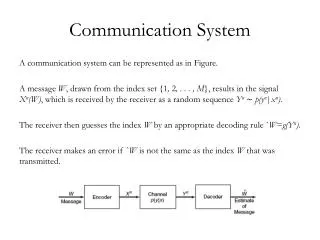
: # of bits per data block : # of Repetitions : Orthogonal code length : # of repetitions : Code length : Pulse bin width (duration) : Multi-coded chip duration : Position number for BPPM : Multi-coded symbol duration : Guard time for processing delay : Total transmit time duration of a data block PHY Frame Structure • Frame Structure of PPDU Preamble SFD PHR PSDU
1 1 -1 1 -1 1 -1 1 -1 -1 -1 1 1 1 1 -1 -1 -1 1 -3 1 1 1 -1 -1 1 1 -1 -1 1 1 MC-PPM • Operation Concept (e.g. L=3, Ns=4, Nr=1, Tg=0 ns) Multi-coded symbol ( Code rate : L/Ns ) Ex. Code rate = 3/4 Orthogonal code set ( Code Length : Ns ) Ex. Ns=4 Data block ( L bits ) Ex. L=3 Modulation PPM : 1 -3 1 1
MC-PPM (Cont’d) • Tg = 0 • Tm=200nsec, Ton=20nsec • Bit rate : 1kbps • L=3, Ns=8, Nr=1 [Td=Td_on+Td_off=(L+1)*Ns*Tm+467+Td_on] • L=3, Ns=16, Nr=1 [Td=Td_on+Td_off=(L+1)*Ns*Tm+467+Td_on] Ton Tm
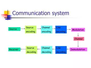
Data Encoder Data Modulator Data Orthogonal Channel Bi-phase PPM Multi-code Pulse Generator Data Data Decoder Data DeModulator Orthogonal Bi-phase PPM Multi-code Pulse Location Generator Detector Transceiver Architecture • Transmitter • Receiver
Signal Robustness • Proposed Operating Bandwidth : 3-5GHz • Operating Bands for Pre-existing Services • IEEE 802.15.1 -> 2.4GHz Band • IEEE 802.11b,g -> 2.4GHz Band • IEEE 802.11a -> 5 GHz Band • Interference and Coexistence Problems with Pre-existing Services • The operating bandwidth is occupying different band compared to pre-existing services
PHY-SAP Payload Bit Rate and Data Throughput PPDU PHY PREAMBLE PHY HEADER MPDU = PSDU T preamble T header MHR (Frame Control +Seq. Num +Addr Fields) MSDU (Data payload) MFR (FCS)
PPDU Structure • FCS (Frame Check Sequence) • 16 bit ITU-T CRC • Calculated over the MHR and MAC payload part • X16+x12+x5+1 • Preamble • Use 4 bytes • For further performance improvements, the size and preamble pattern will be defined
Simultaneously Operating Piconets (SOP) • Time Division • Operating bandwidth • 3.1-4.9 GHz can be fully used (UWB pulse) • Configuration of SOPs • Self configuration of SOPs is possible by modified passive scan Piconet#1 Active Inactive Piconet#2 Piconet #3
Modified Passive Scan • Usages • Starting a new PAN (FFD) • Association (FFD or RFD) • Channel Scan • Modify passive scan procedures (IEEE 802.15.4 spec.) • Repeat scanning one channel (3-5 GHz) until correctly receiving beacons from each piconet coordinator • Get the information of piconets • Timing information, system parameters, and etc… • Operations of Coordinator and Device • Prior to starting a new PAN (FFD) • Transmit its own beacon • Prior to association (FFD or RFD) • Associate with a desired piconet coordinator
preamble preamble Chaotic Synchronization • Non-coherent Chaotic Synchronization Procedure • Assume N_int square-law integrators • Divide T_m time into total N_int time slots (each time slot contains T_m/N_int time) • t_s : sync. starting point / t_sync : exact sync. point
Chaotic Synchronization (Cont’d) • Non-coherent Chaotic Synchronization Procedure • The output value of n-th square-law integrator • Estimated Sync. Point
Chaotic Synchronization (Cont’d) • Chaotic Synchronization Parameters • Pseudo Chaotic Pulse [BW=2GHz(3G-5GHz), Tp=20ns] • Preamble Length • 32 Bytes (1 Bytes = 8 Chaotic Pulses) • Tm=200ns, Ts=100ns (Ts=Ns*Tp -> Ns=5) • Preamble Time Duration = 5.2us • Number of Integrators (Nint) = 10 • In HW Implementation, 5 Integrators can considered • Relative Preamble Length = 32 Bytes/(Nint/5)=16 Bytes • Synchronization Resolution [Tm/(2*Nint)] = 10ns