Download
1 / 35
350 likes | 508 Views
Development of a Precise and Fast Multistream Scattering-Based DMRT model with Jacobian . Miao Tian A.J. Gasiewski . University of Colorado Department of Electrical Engineering Center for Environmental Technology Boulder, CO, USA. Motivation for a UMRT.

E N D
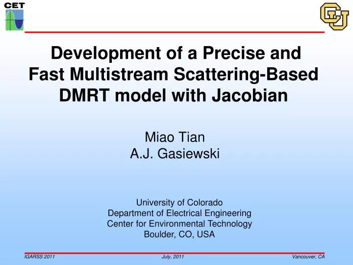
Development of a Precise and Fast Multistream Scattering-Based DMRT model with Jacobian Miao Tian A.J. Gasiewski University of Colorado Department of Electrical Engineering Center for Environmental Technology Boulder, CO, USA
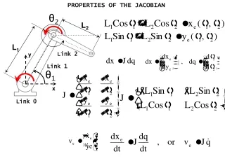
Motivation for a UMRT * Voronovich, A.G., A.J. Gasiewski, and B.L. Weber, "A Fast MultistreamScattering Based Jacobian for Microwave Radiance Assimilation,“ IEEE Trans. Geosci. Remote Sensing, vol. 42, no. 8, pp. 1749-1761, August 2004.
UMRT: Medium Model • In UMRT, a planar-stratified model is used. • Categorized into Upper-half, Sparse Medium 1) Upper-half, Sparse medium: a) General atmosphere b) Weakly homogeneous and slightly dissipative c) Independent scattering: scattering intensity is the sum of scattering intensities from each particle. d) Particle size distribution function e) Sparse medium radiative transfer Lower-half, Dense Medium 2) Lower-half, Dense medium: a) Ice, snow, soil and etc., b) Inhomogeneous and strongly dissipative c) Multiple volumetric scattering: scattering intensity is related to the presence of other particles. (from Golden et al., 1998) d) Pair distribution function (Percus-Yevick Approximation). e) Dense medium radiative transfer (DMRT) by Tsang and Ishimaru • Specular interface and Snell’s law are applied at each layer boundary. • Not included yet: rough surface interfaces (ice ridges, rough soil, etc…)
Mie Phase Matrix: Flowchart Reduced Mie Phase Matrix P’(θs,θi) Isotropic Sphere Sphere Modified Stokes MatrixL(θs,θi;Δϕ) Mie Phase Matrix P(θs,θi; Δϕ) Angular Functions (πn, τn) Modified Stokes matrixL(Θ) Parameters (m, x) Scattering Angle (Θ) Interpretation of (i1,2) Mie Coefficients (an, bn) Rotation MatrixLr(i1,2) Under the assumptions: 1) Isotropy and 2) Sphericity
Mie Stokes Matrix For Mie Scattering (van de Hulst, 1981; Bohren and Huffman, 1983), 2) The Stokes rotation matrix is 1) Interpretation of i1 and i2 where and are the Mie coefficients;and are the angle-dependent functions. where and
Stokes Matrix: Symmetry The normal incident and scattered angles based Stoke matrix is Is = ? Subtraction Results (General) Symmetryof Stokes matrix is divided into two cases. ? = The subtraction results of both cases have similar expressions for general Stokes matrices. Subtraction Results (Mie) Thus, Stokes matrix is generally symmetric for the first two Stokes parameters. For the Mie Stokes matrix, the above subtraction results has following formation: Thus, the Mie Stokes matrix is symmetric for the first three Stokes parameters. Finally, the Rayleigh Stokes matrix is symmetric for all four Stokes parameters.
Reduced Phase Matrix θs θi dθi dθs
Reduced Mie PM: Validation The reduced Mie phase matrix can be numerically calculated. The 3rd and 4th Stokes parameters are independent of the first two Stokes parameters and can be calculated separately. Reduced Rayleigh phase matrix (179x179 angles) Same <D> and frequency Reduced Mie phase matrix: MP(rate)=10 mm/hr, <D>=2 mm, freq = 3 GHz (32x32 quadrature angles) Each plot: Up-Left corner: , Forward Scattering Up-Right corner: , Backward Scattering
Reduced Mie Phase Matrix freq = 100 GHz freq = 30 GHz freq = 300 GHz freq = 1000 GHz
DMRT-QCA Phase Matrix • Incorporates latest version of DMRT-QCA by Tsang, et al., 2008. • A prominent advantage: simplification of the phase matrix calculation • Summary of the DMRT-QCA procedure: Lorentz-Lorentz (L-L) law: effective propagation constant Ewald-Oseen theorem with L-L law: the average multiple amplitudes: The absorption coefficient is calculated as a function of Percus-Yevick approximation: structure factor Applying all above parameters, the DMRT-QCA phase matrix is calculated by Applying same rotation and azimuthal integration procedure, the reduced DMRT-QCA phase matrix can be calculated.
PM Comparison: Mie vs. DMRT (1) Non-sticky particle case mean diameter: 0.14cm fractional volume: 25% frequencies: 13.4GHz, 17.5GHZ, 37GHz 2) DMRT-QCA predicts more forward scattering than that of the Mie theory Validation to “Modeling active microwave remote sensing of snow using DMRT theory with multiple scattering effects”, IEEE, TGARS, Vol.45, 2007, by L. Tsang et al.,
PM Comparison: Mie vs. DMRT (2) Sticky particle case: mean diameter: 0.14cm fractional volume: 25% frequencies: 13.4GHz, 17.5GHZ, 37GHz 2) DMRT-QCA sticky case predicts much greater forward scattering than that of the Mie theory Validation to “Modeling active microwave remote sensing of snow using DMRT theory with multiple scattering effects”, IEEE, TGARS, Vol.45, 2007, by L. Tsang et al.,
Reduced DMRT Phase Matrix 30 GHz 10 GHz DMRT-QCA phase matrix over 16 quadrature angles Sticky particle case: mean diameter: 0.14 cm fractional volume: 25% 100 GHz
UMRT: Discretizition Numerical DRTE for first two Stokes parameters where The boundary conditions are: Separate the up- (+) and down- (-) welling components of radiation. Let Use the Gauss-Legendre quadrature with the Christoffel weights . and Symmetrizing variables
UMRT: Symmetrization For vertical polarization, let Similarly, for horizontal polarization, let Note: 1) The matrices and are symmetric. In UMRT, 2) Making use of Gershgorin’s circle theorem (see Voronovichet al., 2004), it was shown that the matrices and are positive definite, since following condition always hold in RT: The argument of symmetric, positive definite (SPD) matrices and holds throughout the entire UMRT algorithm.
Discrete Ordinate-Eigenanalysis Step 1. Make following linear transformation. Step 2. The DRTE becomes , where Step 3. Decouple the two equations Step 4.1 There are two primary methods to solve equations of step 3. For example, Tsang (L. Tsang, et al., 2000) uses: Step 4.2 In UMRT, we use the solution given by A. Voronovich et al., 2004. by making use of the matrix identity for symmetric matrices: where
UMRT: Solution for Single Layer Applying B.C, at z = h Similarly, tuinc Positive definite: eigenvalues are non-negative, thus guarantees that exists. Details can be found in DOTLRT, Voronovich et al., 2004 Δz uinc ruinc Symmetry: To calculate the reflective and transmissive matrices, When x , tanh(x) and coth(x) are bounded to 1. When sinh(x) , sinh-1(x) is small (invertible).
UMRT: Solution for Single Layer (2) Inhomogeneoussolution of the DRTE In DOTLRT, the up- and down- welling radiations are both assumed independent with height. Assume: Under the assumption of mirror symmetry, the up- and down- welling self-radiation are also equal. uinh uinh ruinh (b) uinh tuinh In UMRT, the up- and down- welling radiations are both assumed to be linear with height. (c) Layer Centric By applying conventional block (2x2) matrix inversion,
UMRT: Solution for Single Layer (3) and Validation of above solutions can be done by reducing the case to DOTLRT: if t3 = 0, then t1 =t2 = 0. From where, we find Similarly, Finally, the inhomogeneous solution in UMRT is
UMRT: Recursive Solution for Multilayer In UMRT, the up- and down- welling self-radiations of a single layer are not the same, thus: -tvinh -vinh -vinh uinh -rvinh (a) -uinh vinh -ruinh -uinh -tuinh Level Centric (b) (c)
UMRT: Recursive Solution for Multilayer (3) Finally, we have following recursive solutions in UMRT: Note: Matrices and for all individual layers should be first obtained. The initial conditions are Critical angle and Interpolation: 1) Only the incident streams that are inside the critical angle will pass through the interface. 2) Such refractive streams are bent from the quadrature angles. UMRT employs the cubic spline interpolation to compensate them back to the quadrature angles 3) The incident streams whose angle are greater than critical angle will be remove for upwelling radiation streams and added back to the corresponding downwelling radiation streams. Finally, the UMRT solutions are modified as
UMRT: Jacobian Procedure UMRT Jacobian Procedure Key: , ,, , , , ,, ,, , w.r.t: , , , , ,,
Summary UMRTis developed based on the DOTLRT concept, however, it has following key improvements: The symmetry property of the polarized reduced Mie phase matrix is exploited so that the applicability of the fast and stable matrix operation (based on symmetry and positive definiteness) is applicable to both sparse and dense media. Mie phase matrix is applied so that radiation coupling is included in a fully polarimetric solution. DMRT-QCA phase matrix is included for dense medium layers describing (e.g.) vegetation, soil, ice, seawater, etc… The physical temperature of a layer is linear in height, allowing the precise solutions for piecewise linear temperature profiles, thus extending the applicability of DOTLRT to a level-centric grid. The refractivity profile is accounted for by including the critical angle effect and applying cubic spline interpolation to a refractive transition matrix (not discussed).
Mie Stokes Matrix: Validation (a) (b) Normalized Mie Stokes matrix elements for single particle: particle diameter =1.4 mm, material permittivity (ice) = 3.15-j0.001: a) freq = 13.4GHz; b) freq = 37GHz. Replica of Fig. 3 in “Modeling active microwave remote sensing of snow using DMRT theory with multiple scattering effects”, IEEE, TGARS, Vol.45, 2007, by L. Tsang et al.,
Mie Stokes Matrix: Validation (2) (a) P33 is asymmetric to 90o and P33(at 0o) is greater than P33(180o). P34 is symmetric to 90o. Qualitative validation by the description in Thermal Microwave Radiation Applications for Remote Sensing, 2006, ch.3, A. Battagliaet al., edited by C. Matzler. (b)
UMRT: Recursive Solution for Multilayer u* vinc tvinc v*=u* In DOTLRT, the self-radiation of each layer is same in the up- and down- welling directions, ( ) thus: where and are the multiple reflections between the extra top layer and the stack. If there exists an external downwelling radiation vinc, it will result in the presence of two additional up- and downwelling field and , which must satisfy:
UMRT: Critical Angle and Interpolation Atmosphere (natm) … … … Superposition to the self-radiation of this layer Snow (nsnow) … … … … Ice (nice) … In both UMRT and DOTLRT, once the number M is chosen, the quadrature angles are then fixed in each layer (for self-radiation). Only the refractive streams whose incident streams are inside the critical angle will successfully pass through the interface. Such refractive streams are bended and generally away from the quadrature angles. Therefore need to be correctly compensated back to the fixed quadrature angles. The incident streams whose angle are greater than critical angle will be remove for upwelling radiation streams and added back to the corresponding downwelling radiation streams. Critical angle: the angle of incidence above which total internal reflection occurs. It is given by
Mie Scattering and Extinction Spherical Mie scattering 2) Monodispersed spherical particle b) Natural raindrop distribution: Marshall and Palmer (MP) SDF c) Ice-sphere distribution: Sekhon and Srivastava SDF d) The absorption coefficient is where and are spherical Bessel and Hankel functions of the 1st kind. is the size parameter and Polydispersed spherical particles a) With size distribution function (SDF): Details can be found in M. Jansen, Ch.3 by A. Gasiewski, 1991.
Validation of Mie Absorption and Scattering Replica of Fig.3.6-7 in Chapter 3 (right side), originally produced by A. Gasiewski, Atmospheric Remote Sensing by Microwave Radiometry, edited by M. Janssen, 1993.
For Mie Scattering (van de Hulst, 1981; Bohren and Huffman, 1983), Mie Stokes Matrix Under the assumptions: 1) Isotropy and 2) Sphericity where and are the Mie coefficients;and are the angle-dependent functions as Figure from Scattering of Electromagnetic Waves, vol. I, p.7 by L. Tsang, et al., 2000
Reduced Mie PM: 10 GHz Below ~60 GHz: Forward scattering ~ Backward scattering 2) Above ~60 GHz: Forward scattering > Backward scattering 3) P12is 90o rotation to P21. 4) P34= -P43 5) P44is greater than P33
Δz Δz