Download
1 / 29
310 likes | 539 Views
Data Movement Instructions. Chapter 4. MOV Revisited. The MOV instruction introduces the ma-chine language instructions available with various addressing modes and instructions

E N D
Data Movement Instructions Chapter 4
MOV Revisited • The MOV instruction introduces the ma-chine language instructions available with various addressing modes and instructions • It is the native binary code that the micro-processor understands and uses as its instructions to control its operation • See the format of the instructions in Fig. 4.1
MOV Revisited (cont’d) • The Opcode • The opcode selects the operation (addition, subtraction, move, etc) performed by the microprocessor • The opcode is either one or two bytes long for most machine language instructions (Fig.4.2) • The first six bits of the first byte are the binary op-code • The remaining two bits indicate the direction (D) of the data flow and whether the data are byte or a word (W)
MOV Revisited (cont’d) • Refer to Fig.4.3 for the binary bit pattern of the second opcode byte (reg-mod-r/m) • MOD field • The MOD field specifies the addressing mode (MOD) or the type of addressing for the selected instruction, and whether the displace-ment is present with the selected type (table 4.1) • Distinguish the MOV AL, [DI], MOV AL, [DI+2] and MOV Al, [DI+1000H]!
MOV Revisited (cont’d) • Register Assignments • Table 3.3 lists the register assignments for the REG field and the R/M field (MOD=11) • Examine the 8BECH binary instruction (Fig.4.4) • R/M Memory Addressing • If the MOD field contains a 00, 01, or 10, the R/M field takes on a new meaning (Table 4.4) • Figure 4.5 illustrates the machine language version of the 16-bit instruction MOV DL,DI or instruction (8A15H)
MOV Revisited (cont’d) • Special Addressing Mode • It occurs whenever memory data are referenced by only the displacement mode of addressing for 16-bit instruction s ---> MOV [1000H],DL • Whenever an instruction has only a displace-ment, the MOD field is always a 00 and the R/M field is always a 110 (see Fig.4.6, Fig.4.7) • 32-bit Addressing • Table 4.5. Shows the coding for R/M used to specify the 32-bit addressing modes
MOV Revisited (cont’d) • The scaled-index byte (R/M=100) is mainly used when two registers are added to specify the memory address in an instruction (Fig.4.8)
MOV Revisited (cont’d) • An Immediate Instruction • suppose the instruction MOV WORD PTR [BX +1000H], 1234H that moves 1234 into the word-sized memory location addressed by the sum of 1000H, BX, and DS x 10H • The six byte instruction uses two bytes for the op-code, W, MOD, and R/M fields, two other bytes are the data of 1234H, and the last two are the displacement of 1000H See Fig.4.9
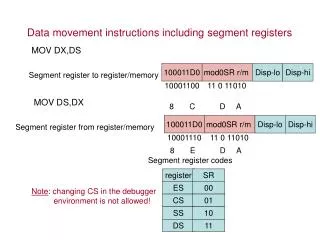
MOV Revisited (cont’d) • Segment MOV Instructions • If the contents of a segment register are moved by the MOV, PUSH, or POP instructions, a special set of register bits (REG field) selects the segment register (see Table.4.6) • Figure 4.10 shows a MOV BX,CS instruction converted to binary • The op-code is different for the prior MOV • Segment registers can be moved between any 16-bit memory location or 16-bit memory location
PUSH/POP • These are important instructions that store and retrieve data from the LIFO stack memory • There are six forms of the PUSH and POP instructions: register, memory, immediate, segment register, flags, and all registers • PUSH • It transfer two or four bytes of data to the stack • PUSHA instruction copies the contents of the internal register set, except the segment registers to the stack
PUSH/POP (cont’d) • The PUSHA (push all) instruction copies the registers to the stack in the following order: AX, BX, CX, DX, BX, SP, BP, SI, and DI • The PUSHF (push flags) instruction copies the content of the flag register to the flack • Figure 4.11 shows the operation of the PUSH AX • AX --> SS:[SP-1] = AH, SS:[SP-2] = AL, and after- ward SP = SP - 2 • Figure 4.12 illustrates the result of the PUSHA instruction
PUSH/POP (cont’d) • Table 4.7 lists the forms ofthe PUSH instruction • POP • It performs the inverse operation of PUSH, i.e., removes data from the stack and places it into the target 16-bit register, or a 16-bit memory location • POPF (pop flags) removes 16-bit number from the stack and places it into the flag register • The POPFD removes 32-bit number from the stack & places it into the extended flag register
PUSH/POP (cont’d) • The POPA (pop all) removes 16-bit data from the stack and places it into the following registers in order: DI, SI, BP, SP, BX, DX, CX, and AX; this is a reverse order from the way they are placed on the stack by the PUSHA • Figure 4.13 shows how the POP BX removes data from stack into BX • Table 4.8 lists the op-codes used for the POP and all of its variations
PUSH/POP (cont’d) • Initializing the Stack • If the stack area is initialized, load both the SS and SP registers; SS is normally designated with the bottom location of the stack segment • Fig.4.14 shows how the beginning of stack segment is formed and used in PUSH CX • A stack segment is set up as illustrated in example 4.1 and example 4.2