Download
1 / 35
350 likes | 464 Views
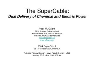
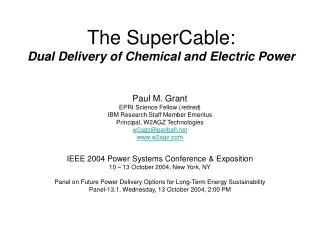
www.w2agz.com/cec-icmc05.htm. Cryo-Delivery Systems for the Co-Transmission of Chemical and Electrical Power. Paul M. Grant Visiting Scholar in Applied Physics, Stanford University EPRI Science Fellow ( retired ) IBM Research Staff Member Emeritus Principal, W2AGZ Technologies

E N D
www.w2agz.com/cec-icmc05.htm Cryo-Delivery Systems for the Co-Transmission of Chemical and Electrical Power Paul M. Grant Visiting Scholar in Applied Physics, Stanford University EPRI Science Fellow (retired) IBM Research Staff Member Emeritus Principal, W2AGZ Technologies w2agz@pacbell.net www.w2agz.com CEC – ICMC 2005 29 August – 2 September 2005, Keystone, CO Paper C1-101, Cryofuels Session30 August 2005, 10:30 AM
Past & Future Energy Supply Relative Units Year (Modern Era)
H2 + Fission Nukes Past & Future Energy Supply Relative Units Year (Modern Era)
Its Solution A Symbiosis of Nuclear/Hydrogen/Superconductivity Technologies supplying Carbon-free, Non-Intrusive Energy for all Inhabitants of Planet Earth SuperCities & SuperGrids SuperCables !
5 Miles California Coast Power Diablo Canyon 2200 MW Power Plant Wind Farm Equivalent
Co-Production of Hydrogen and Electricity Reactor Vessel O2 Source: INEL & General Atomics
SuperCity School H2 Home Supermarket Family Car Nuclear plant H2 DNA-to-order.com HTSC/MgB2 P.M. Grant, The Industrial Physicist, Feb/March Issue, 2002
+v I I -v H2 H2 H2 H2 Circuit #1 “Hydricity” SuperCables Bartlit, Edeskuty, & Hammel (1972) +v I I -v Multiple circuits can be laid in single trench Circuit #2
SuperCable Monopole HV Insulation tsc “Super-Insulation” DH2 Superconductor DO Hydrogen
Electricity PSC = 2|V|IASC, where PSC = Electric power flow V = Voltage to neutral (ground) I = Supercurrent ASC = Cross-sectional area of superconducting annulus Hydrogen PH2 = 2(QρvA)H2, where PH2 = Chemical power flow Q = Gibbs H2 oxidation energy (2.46 eV per mol H2) ρ = H2 Density v = H2 Flow Rate A = Cross-sectional area of H2 cryotube Power Flows
Hydricity Scaling Factor Dimensionless, geometry-independent scaling factor defines relative amounts of electricity/hydrogen power flow in the SuperCable: “Pressure” “Energy Density”
Electricity Power (MW) Voltage (V) Current (A) Critical Current Density (A/cm2) Annular Wall Thickness (cm) 1000 +/- 5000 100,000 25,000 0.125 Hydrogen (LH2, 20 K) Power (MW) Inner Pipe Diameter, DH2 (cm) H2 Flow Rate (m/sec) “Equivalent” Current Density (A/cm2) 500 10 3.81 318 Electric & H2 Power
Thermal Losses Radiation Losses WR = 0.5εσ (T4amb – T4SC), where WR = Power radiated in as watts/unit area σ = 5.67×10⁻¹² W/cm2K4 Tamb = 300 K TSC = 20 K ε = 0.05 per inner and outer tube surface DSC = 10 cm WR = 3.6 W/m Superinsulation: WRf = WR/(n-1), where n = number of layers Target: WRf = 0.5 W/m requires ~10 layers Other addenda (convection, conduction): WA = 0.5 W/m WT = WRf + WA = 1.0 W/m
Heat Removal dT/dx = WT/(ρvCPA)H2, where dT/dx = Temp rise along cable, K/m WT = Thermal in-leak per unit Length ρ = H2 Density v = H2 Flow Rate CP = H2 Heat Capacity A = Cross-sectional area of H2 cryotube Take WT = 1.0 W/m, then dT/dx = 1.8910-5 K/m, Or, 0.2 K over a 10 km distance
SuperCable H2 Storage One Raccoon Mountain = 13,800 cubic meters of LH2 LH2 in 10 cm diameter, 250 mile bipolar SuperCable = Raccoon Mountain
T = 77 K P = 6800 psia Crude Phase Diagram of H2
1.2 1 0.8 Rho(H2)/Rho(LH2) Supercritical 100% LH2 0.6 0.4 50% LH2 0.2 Vapor 0 0 2000 4000 6000 8000 10000 Pressure (psia) Relative Density of H2 as a Function of Pressure at 77 K wrt LH2 at 1 atm H2 Gas at 77 K and 1850 psia has 50% of the energy content of liquid H2 and 100% at 6800 psia
Electrical Insulation “Super-Insulation” Liquid Nitrogen @ 77 K Superconductor Supercritical Hydrogen @ 77 K 1000 – 7000 psia Supercritical H2 SuperCable
Fluid Properties Comparison of Liquid to Gaseous Hydrogen Transporting 500 MWt in a 10-cm Diameter Pipe Thus, it takes only 0.5 dynes “push” on an object with the above Reynolds Numbers on the gas to overcome viscous forces exerted by the given fluid
Fluid Friction Losses Wloss = M Ploss / , Where M = mass flow per unit length Ploss = pressure loss per unit length = fluid density
Nuclear Singlet (Para) – Triplet (Ortho) H2 Electronic
21 K 77 K % para-H2 in Normal H2
An Unanswered Question (?) • Is the para-ortho ratio dependent on magnetic field? • The peripheral field from a 100 kA superconductor cable can reach 1 T or greater. • Will this magnitude field induce a para-to-ortho spin flip? (maybe to 100% ortho?) • At 77 K, H2 is 50/50 para/ortho, and the ortho-para transition is exothermic with an enthalpy release of 523 kJ/kg. • Would a loss of electric current with concurrent magnetic field collapse result in an ortho-para transition and subsequent heating?
The Mackenzie Valley Pipeline http://www.mackenziegasproject.com 1220 km 18 GW-thermal 2006 - 2009
2004 Natural Gas End Use Schoenung, Hassenzahl and Grant, 1997 (5 GW on HTSC @ LN2, 1000 km) Why not generate this electricity at the wellhead?
Electrical Insulation “Super-Insulation” Thermal Barrier to LNG Liquid Nitrogen @ 77 K Superconductor LNG @ 105 K 1 atm (14.7 psia) LNG SuperCable Design for eventual conversion to high pressure cold or liquid H2
SuperCable Parameters for LNG Transport CH4 Mass Flow (12 GW (HHV)) 230 kg/s @ 5.3 m/s LNG Density (100 K) 440 kg/m3 LNG Volume Flow 0.53 m3/s @ 5.3 m/s Effective Pipe Cross-section 0.1 m2 Effective Pipe Diameter 0.35 m (14 in) MVP Wellhead Electricity Electricity Conversion Assumptions
It’s 2030 • The Gas runs out! • Build HTCGR Nukes on the well sites in the Mackenzie Delta (some of the generator infrastructure already in place) • Use existing LNG SuperCable infrastructure to transport protons and electrons • Electricity/H2 split needs to be determined…Now!
Take-Home Reading Assignment www.w2agz.com/cec-icmc05.htm • Garwin and Matisoo, 1967 (100 GW on Nb3Sn) • Bartlit, Edeskuty and Hammel, 1972 (LH2, LNG and 1 GW on LTSC) • Haney and Hammond, 1977 (Slush LH2 and Nb3Ge) • Schoenung, Hassenzahl and Grant, 1997 (5 GW on HTSC @ LN2, 1000 km) • Grant, 2003 (“Hydrogen Lifts Off…,” Nature) • Grant, 2005 (The SuperCable) • SuperGrid Workshop, 2004 (See Bibliography)