Download
1 / 9
90 likes | 99 Views
Summary so far: • Free, undamped, linear (harmonic) oscillator • Free, undamped, non-linear oscillator • Free, damped linear oscillator Starting today: • Driven(!!!), damped linear oscillator • Laboratory to investigate LRC circuit as example of driven, damped oscillator.

E N D
Summary so far: • Free, undamped, linear (harmonic) oscillator • Free, undamped, non-linear oscillator • Free, damped linear oscillator Starting today: • Driven(!!!), damped linear oscillator • Laboratory to investigate LRC circuit as example of driven, damped oscillator
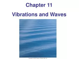
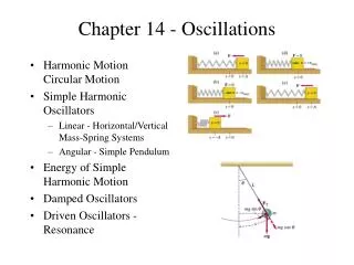
THE DRIVEN, DAMPED HARMONIC OSCILLATOR Reading: Main 5.1, 6.1 Taylor 5.5, 5.6 WE’LL DO EXPERIMENT TODAY, & THE THEORY TOMORROW!
Natural motion of damped, driven harmonic oscillator viscous medium k F0coswt m k m x Note w and w0 are not the same thing! • is driving frequency w0 is natural frequency
Natural motion of damped, driven harmonic oscillator L I C R Vocoswt Apply Kirchoff’s laws http://www.sciencejoywagon.com/physicszone/lesson/otherpub/wfendt/accircuit.htm
L I C R Natural (resonance) frequency determined by the inductor and capacitor Damping determined by the resistor & inductor LRC circuit LCR circuit obeys precisely the same equation as the damped mass/spring. Typical numbers: L≈500µH; C≈100pF; R≈50W w0≈106s-1 (f0≈700 kHz) t=1/b≈2µs; (your lab has different parameters)
STEP #1: Build a LRC • Circuit • Vin should be a ~1 kHzsinusoid to start • Vout is measured across the resistor Vout(mv) Function generator, drives circuit AC Vout Vin tune the frequency knob Vin Vout(mv)
STEP #2: Figure out the oscilloscope Measure the frequency! Menu off button “push”=enter “ctrl-alt-del” for osc V save to usb drive t Put cursor in track mode, one to track ch1, one for ch2 measure Vout across R Vin to func gen
STEP #3: get your data!!!“crest to crest” Vin (mV) Vout(mv) Dx (t) Vin AC frequency of Vin
STEP #4: Record your data (in an Excel table or software of your choice) + save a representative data trace Upload to CANVAS before class tomorrow for 5 points fill out a table like this with data form the oscilloscope Choose your frequenciesintelligently! (~8 well placed measurements is enough) Step #5:Upload your data to CANVAS before class tomorrow for 5 lab points. You’re now DONE! Congrats!