Download
1 / 17
170 likes | 290 Views
Design window analysis of LHD-type Heliotron DEMO reactors. Fusion System Research Division, Department of Helical Plasma Research, National Institute for Fusion Science Takuya GOTO, Junichi MIYAZAWA, Teruya TANAKA, Nagato YANAGI and Akio SAGARA

E N D
Design window analysis of LHD-type Heliotron DEMO reactors Fusion System Research Division, Department of Helical Plasma Research, National Institute for Fusion Science Takuya GOTO, Junichi MIYAZAWA, Teruya TANAKA, Nagato YANAGI and Akio SAGARA Special thanks to Dr. Y. Suzuki, Prof. F. Najmabadi Japan-US Workshop on Fusion Power Plants and Related Advanced Technologies with participations of EU and Korea February 22-24, 2011, NIFS, Toki, JAPAN
LHD-type Heliotron DEMO is foreseeable • Helical system with net-current free plasma: • No disruptive event steady-stateeasily achievable • No current drive powerself-ignition state (Q = ∞)is attainable • LHDhas achieved: • High beta(~5% by volume average for ~100tE) • Extremely high central density (IDB-SDC, ne0 = 1.2×10²¹m-3 ) • Steady statewo/ disruptive events • Other remarkable observations • Impurity hole • Divertor detach scenario *Figure from A. Komori et al., Fusion Science and Technology 58 (2010) 1. • The LHD-type Heliotron DEMO reactor is foreseeable. T. Goto, J-US WS on Fusion Power Plants and Related Advanced Technologies, 2011.2.22-24
Not optimum but ‘robust’ design There are several uncertainties in the physics conditions of a burning plasma. Density and temperature profiles Impurity fraction (especially helium ash fraction fa) Alpha heating efficiency ha DEMO is the next step reactor high reliability is required in its design Direct extrapolation of experimentally-obtained plasma properties (presented by Dr. Miyazawa) Finding of robust (insensititive to the change of uncertain parameters) design window T. Goto, J-US WS on Fusion Power Plants and Related Advanced Technologies, 2011.2.22-24
System Design Code HELIOSCOPE HELIOtron System design COde for Performance Evaluation Parameter input Coil design parameters Rc, ac, g , a, jc, Ic, W/H, … Plasma parameters an, aT, fimp, ne0, Te0, … Coil and magnetic surface structure Bmax, Wmag, D, … Plasma performance `ne , Wp, Pfus, Prad, tE, HISS, <b>, nsudo, … Magnetic surface configuration <Bt>, <ap>, Rgeo, … Plant power flow Pn, Pth, Pe, Gn, Gdiv, … Database of magnetic surface structure (vacuum equilibrium calculation) T. Goto, J-US WS on Fusion Power Plants and Related Advanced Technologies, 2011.2.22-24 T. Goto, J-US WS on Fusion Power Plants and Related Advanced Technologies, 2011.2.22-24
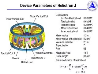
LHD-type Heliotron Reactor FFHR-2m2 FFHR-2m2* is the LHD-type Heliotron reactor Based on LHD high-beta discharge designed for the use in both a DEMO and commercial reactor • Design policy: • Pfus = 3GWth (Pe,net = 1GWe) • Long-term (~30 FPYs) operation with high plant availability • Average neutron wall load<Gnw > < 1.5 MW/m2 is assumed • Technology can be extrapolated from the present knowledge • Stored magnetic energy Wmag < 160 GJ is assumed** * A. Sagara et al.,. Fus. Eng. Des. 83, 1690 (2008), A. Sagara et al.,. Nucl. Fusion 45, 258 (2005). ** S. Imagawa et al.,. Nucl. Fusion 49, 075017 (2009). T. Goto, J-US WS on Fusion Power Plants and Related Advanced Technologies, 2011.2.22-24 T. Goto, J-US WS on Fusion Power Plants and Related Advanced Technologies, 2011.2.22-24
Blanket space is a key design issue Inboard side blanket space on vertically-elongated cross-section is limited for the LHD-type heliotron reactor Inboard minimum blanket space Din> 1.0m is assumed in FFHR-2m2 assure the sufficient net TBR (>1.05) with ~40cm breeding layer suppress fast neutron damage on superconducting coil < 1022n/cm2 after 30FPYs with ~60cm radiation shield T. Goto, J-US WS on Fusion Power Plants and Related Advanced Technologies, 2011.2.22-24 T. Goto, J-US WS on Fusion Power Plants and Related Advanced Technologies, 2011.2.22-24
Physic conditions of FFHR-2m2 Physics conditions: Mainly based on LHD high-beta discharges Inward-shifted magnetic axis position Rax/Rc = 3.6/3.9 Helical pitch parameter g =1.2 (plasma aspect ratio Ap ~ 6.3) Density/temperature profiles as with an=0.25, aT=0.75 Density limit:`ne< 1.5 nsudo Assumingfa=0.03andha=0.9 T. Goto, J-US WS on Fusion Power Plants and Related Advanced Technologies, 2011.2.22-24 T. Goto, J-US WS on Fusion Power Plants and Related Advanced Technologies, 2011.2.22-24
Design point of FFHR-2m2 • Rc=17m,Bt,c=4.7T has been selected by engineering constraints • HLHD~1.3 can realize this design point with the assumed physics conditions • HLHD is quite sensitive to physics conditions • Design point with lower HLHD is favorable T. Goto, J-US WS on Fusion Power Plants and Related Advanced Technologies, 2011.2.22-24 T. Goto, J-US WS on Fusion Power Plants and Related Advanced Technologies, 2011.2.22-24
Flexible DEMO design concept can reduce the minimum blanket space DEMO should demonstrate; steady-state, self-ignition plasma operation and electric power generation integrity of engineering components 30FPYs operation is not needed and higher neutron flux can be accepted Thinner inboard blanket can be realized by Using special material (ZrH1.65, WC, etc) accepting higher neutron flux on superconducting coil Plasma Magnet Breeding layer (Flibe+Be) 32 cm Radiation shield 68 cm Fluence limit for 30FPYs operation ~20cm thinner Courtesy of Dr. Teruya Tanaka (original figure is found in A. Sagara et al., FED 83, 1690 (2008)) T. Goto, J-US WS on Fusion Power Plants and Related Advanced Technologies, 2011.2.22-24 T. Goto, J-US WS on Fusion Power Plants and Related Advanced Technologies, 2011.2.22-24
Reduction in inboard blanket thickness can expand design window FFHR-2m2 With thinner inboard blanket With thinner inboard blanket & higher neutron wall load T. Goto, J-US WS on Fusion Power Plants and Related Advanced Technologies, 2011.2.22-24 T. Goto, J-US WS on Fusion Power Plants and Related Advanced Technologies, 2011.2.22-24
Reduction in the blanket thickness can expand design window • If Din=0.8m and <Gnw >= 2MW/m2 is accepted, design points with • Rc~ 15 m • Pfus= 3.5 GW • HLHD ~1.15 can be selected • Design robustness of DEMO reactor to the change in the physics conditions T. Goto, J-US WS on Fusion Power Plants and Related Advanced Technologies, 2011.2.22-24 T. Goto, J-US WS on Fusion Power Plants and Related Advanced Technologies, 2011.2.22-24
Summary • Reduction in the minimum blanket thickness can greatly expand the design window • Major radius can be reduced by ~2m • give the robustness to the change in physics conditions • can adopt flexible magnetic configurations • Progress in engineering research that enables the reduction of the minimum blanket space and acceptance of higher neutron wall load is expected. • Larger confinement improvement is also expected to make DEMO and commercial reactors more economically attractive T. Goto, J-US WS on Fusion Power Plants and Related Advanced Technologies, 2011.2.22-24 T. Goto, J-US WS on Fusion Power Plants and Related Advanced Technologies, 2011.2.22-24
Adjustment of poloidal coil position Adjustment of poloidal coil position enables the increase of blanket space as well as increase of plasma volume(~22%). w/ adjustment w/ adjustment wo/ adjustment wo/ adjustment T. Goto, J-US WS on Fusion Power Plants and Related Advanced Technologies, 2011.2.22-24 T. Goto, J-US WS on Fusion Power Plants and Related Advanced Technologies, 2011.2.22-24
High-beta equilibrium analysis Calculation by HINT2 code. <b>~6.5% equilibrium with the almost same volume as that in the vacuum condition can be obtained by applying an appropriate vertical field. Courtesy of Dr. Yasuhiro Suzuki T. Goto, J-US WS on Fusion Power Plants and Related Advanced Technologies, 2011.2.22-24 T. Goto, J-US WS on Fusion Power Plants and Related Advanced Technologies, 2011.2.22-24
Heliotron Reactor Design FFHR-2m2 LHD-type Heliotron reactor which can be utilized as both a DEMO and commercial reactor Design policy: Pfus = 3GWth (Pe,net = 1GWe) Long-term (~30 years) operation with high plant availability Technology can be extrapolated from the present knowledge T. Goto, J-US WS on Fusion Power Plants and Related Advanced Technologies, 2011.2.22-24 T. Goto, J-US WS on Fusion Power Plants and Related Advanced Technologies, 2011.2.22-24
Design constraints of FFHR-2m2 Engineering constraints : Magnet system based on the ITER-relevant technology Helical coil current density:jc=25A/mm2 Magnetic stored energy:Wmag < 160 GJ Minimum blanket space: Dmin> 1m Assure the sufficient net TBR (>1.05) Suppressing fast neutron fluence on SC coil <1022n/cm2 after 30FPY operation) Averaged neutron wall load: <Gnw > < 1.5 MW/m2 Suppressing neutron damage on the structural material <100dpa after 30 FPY operation with long-life blanket concepts Physics condition : Based on LHD high-beta discharges Assuming ne< 1.5 nsudo, fa=0.03andha=0.9. T. Goto, J-US WS on Fusion Power Plants and Related Advanced Technologies, 2011.2.22-24 T. Goto, J-US WS on Fusion Power Plants and Related Advanced Technologies, 2011.2.22-24
3 Key Elements in the LHD-type Heliotron Reactor Designs Maximization of plasma volume, Increase in output vs. Blanket space, Reduction of Wall and divertor loading Increase in magnetic field strength vs. Reduction in stored magnetic energy Plasma ・Beta value ・Confinement improvement SC Coil Blanket/ ・Shield ・Max. field on coil ・Coil current density ・Stored magnetic energy ・Neutron fluence ・Nuclear heating ・Neutron flux ・Thickness ・Materials Increase in the coil cross-sectional area vs. Blanket space • System analysis is necessary to identify design window. T. Goto, J-US WS on Fusion Power Plants and Related Advanced Technologies, 2011.2.22-24 T. Goto, J-US WS on Fusion Power Plants and Related Advanced Technologies, 2011.2.22-24 17/10