Download
1 / 28
290 likes | 515 Views
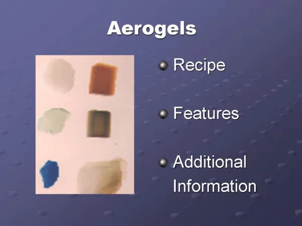
Electroplating of Carbon Aerogels. By Naser Al-Mufachi. Reminder of Aerogels. Its appearance is similar to glass, however resembles solidified smoke. Is a microporous, transparent silicate foam composed of ~99.8% air. It is a stiff foam with a density ranging from 0.1-0.01 g/cm 3 .

E N D
Electroplating of Carbon Aerogels By Naser Al-Mufachi
Reminder of Aerogels • Its appearance is similar to glass, however resembles solidified smoke. • Is a microporous, transparent silicate foam composed of ~99.8% air. • It is a stiff foam with a density ranging from 0.1-0.01 g/cm3. • Is currently the worlds lowest density solid and hence the worlds lightest solid. • Can provide 39 times the insulation capabilities of the best insulating fiberglass material. • 1000 times less dense than glass. • Was used on the Mars Path Finder Rover for insulation. • Can support 500-4000 times its own weight in applied force. • Has a high surface area (250-3000 m2/g).
….and of Carbon Aerogels • Electrically conductive Carbon nanofoams. • Available in forms of monoliths, granules, powders and papers. • The Carbon Aerogel has a high capacitance. • Commonly used as a high temperature insulator, coatings, electrodes fuel cells to name a few.
Carbon family Carbon Aerogel Carbon Felt Carbon Graphite Rod
Initial Approach: Plating with Nickel • In order to get an idea of the electroplating process, a piece of copper sheet was plated with nickel. Adhesion of the Ni plate was excellent and the coating was uniform. • The idea would then be to move onto carbon articles which are similar to that of carbon aerogel. • Carbon Graphite was chosen for its conductive and brittle nature. • Carbon felt was selected for its porous features. • Both of these were used to model the effects and outcome of nickel plating Carbon Aerogels. • Nickel was initially used for plating since it is the easiest to electroplate with in general.
Plating Carbon Graphite • The Carbon graphite rods were prepared by wiping down the outer surface and cleaning with acetone. • The outcome revealed non-uniform plating. • Carbon is difficult to wet since it has a low surface energy. • A wetting agent was selected to help wet the graphite rod. • Different quantities were experimented with in order to decide which was the most effective in plating the rod.
It was observed that at 2% isopropanol in nickel electrolyte solution yielded the best plating. • Conditions: 1.5V for 120 sec • Current readings were increasing during the plating session.
Plating Carbon felt • 2min at 3V in 2% isoprop. solution yielded mild plating on outer surface. • Another sample was done for 5min at 3V in 2% isoprop. Which showed much improved coverage. • This suggests that plating is time dependent. • However, the isopropanol is not ample enough to provide sufficient wetting. • Placing the sample in a vacuum chamber would help draw the air out of the pores and allow the electrolyte solution to infiltrate into the felt
Data collected for felt • The procedure involved attaching a strip of carbon felt to a copper rod. • The sample was then put in a 50ml beaker and sealed at the top using wax paper. • Holes were made to allow for air to pass out. • The sample was then evacuated for 30min runs, electroplated for 30 sec and massed after being further evacuated for 2hrs. • The results show a relative increase in mass however a dramatic drop in mass occurs at 150sec. • Could be put down to the electrolysing of water in the aqueous electrolyte.
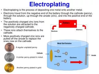
Electroplating Set up • The sample was connected to the black chord which acts as the cathode electrode. • The red chord is attached to the metal desired for plating and plays the role of the anode. • The solution in the beaker is the electrolyte containing freely moving metal ions. • Plating is controlled using the voltage dial.
Preparation method • Samples are typically washed in distilled water and cleaned using acetone. • The samples were then fixed to a paperclip which was connected to a protruding copper wire and immersed in a batch of electrolyte. • The sample was then covered using wax paper and evacuated for 2hrs.
SEM Apparatus • The SEM and FESEM have been used to provide detailed images of the interior plating. • Unfortunately they have been unsuccessful in capturing any images which confirm metal plating. • EDS analysis has confirmed, at least, the presence of metal in the interior.
A large piece of aerogel broke off the original sample, hence the abrupt drop in mass.
In general • Massing the sample after successive plating sessions is a crude technique and yields no real useful data unfortunately. • The adhesion of the outer surface plating is poor and can peel off rendering the mass data inaccurate. • XRD scans are inconclusive and is a technique not suitable for analyzing on the scale being dealt with. • Only real evidence that plating occurs within the carbon aerogel is shown by the EDS scans.
Chromium plated Carbon Aerogel • In the making! • All necessary data should be collected by Monday. • Research will continue.
Acknowledgement • Prof. Young Blood • Prof. Trumble • Ben, Brad, John, Raghavan, Butur, Dave • Entire Materials department. Thank you for your time….Questions?