Download
1 / 17
170 likes | 254 Views
LED Solder Press. Status Report Presentation Senior Projects I By Ryan Bigl & Kyle Levesque. Background Info. This project is for a small business called LEDdynamics, located in Randolph, Vermont.

E N D
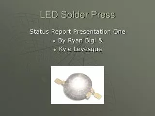
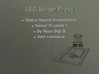
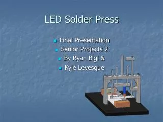
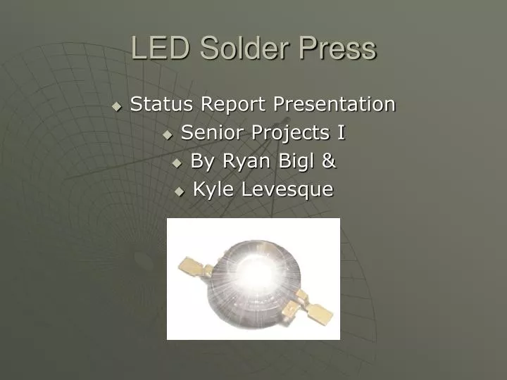
LED Solder Press • Status Report Presentation • Senior Projects I • By Ryan Bigl & • Kyle Levesque
Background Info • This project is for a small business called LEDdynamics, located in Randolph, Vermont. • “LEDdynamics is a custom engineering company specializing in the design and integration of LED technology for end-user and OEM applications.”
Problem statement Design an automated miniature solder press that will… • Be able to solder pre-glued surface mount LED emitters to a metallic circuit board. • Be able to test the LED after completion • Must be faster and more efficient than hand assembly. • System will not need human aid, after initial setup is completed.
Process Description • Drill Metallic Mounting Circuit Board • Prep soldering area with flux • Glue in surface mount LED’s • Solder the LED leads • Test for failed product
Light Strip Base Sizes • Soldering 2 different strip sizes • Soldering 3 different strip styles
Jig Assembly • 2 pull pins • 2 springs • Adjustable slide support • 2 rail / receivers • Base plate • Front support plate
Solutions • Build a X table with a set jig for metallic circuit boards. • Make a single press/ dual soldering iron system with wire fed solder. • Test the LEDs inline with solder station. • Allow user to initially select predetermined board size and stores data throughout the run.
Full System Overview • 1. Controller • 2. Manifold • 3. Power Source • 4. Wire Feed • 5. Push Cylinder • 6. Solder Cylinder • 7. Solder reels • 8. Soldering Tips • 9. Guidance Track • 10. Solder-Testing Frame • 11. User Interface Board • 12. Data Bus • 13. Test Cylinder • 14. Soldering Power Supply • 15. Test Lead
Part Sizes & Tolerances • LED Dimensions Pad Dimension • Both diagrams are drawn with millimeter dimensions • (both diagrams come from Luxeon Emitter, http://www.lumileds.com/pdfs/AB10.PDF
Pneumatic System Overview • This pneumatic system involves; • Double-acting telescopic cylinder • Double-acting cylinder with double-ended adjustable cushioning • Manifold for air flow control • Start push button
Electrical Concepts Twin motor controllers AC to DC power supply LCD Solder Heat units Test unit EStop Triple solenoid block Selector switch Stop/Go Switch
Project Considerations • What are current systems out there doing? X,Y,Z table fully programmable setup • Cost of these systems? $5,000 plus • How fast is LEDDynamics producing these? 8.3hr
Schedule Current status
Project Contacts • Oliver Piluski, LED Dynamics • opiluski@LEDdynamics.com or www.LEDdynamics.com • John Kidder, Senior Projects Teacher • jkidder@vtc.edu • Andre St. Denis, Senior Projects Teacher • ajs05110@vtc.edu