Download
1 / 25
250 likes | 332 Views
Kiyosato , October 2004. Observations of Eruptive Events with Two Radioheliographs, SSRT and NoRH. V.V. Grechnev, A.M. Uralov, V.G. Zandanov, N.Y. Baranov, S.V. Lesovoi. Institute of Solar-Terrestrial Physics Irkutsk, Russia. Outline. Advantages of Observations with Two Radioheliographs

E N D
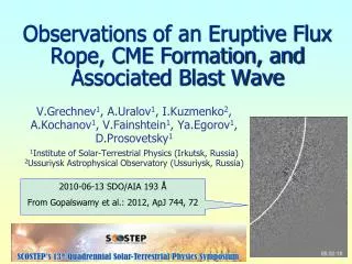
Kiyosato, October 2004 Observations of Eruptive Events with Two Radioheliographs, SSRT and NoRH V.V. Grechnev, A.M. Uralov, V.G. Zandanov, N.Y. Baranov, S.V. Lesovoi Institute of Solar-Terrestrial PhysicsIrkutsk, Russia
Outline • Advantages of Observations with Two Radioheliographs • Three Stages of Filament Eruption: • Pre-eruptive Activation • Rapid Acceleration • Self-Similar Expansion • 1997/09/27: Pre-eruptive Activation of a Prominence • Overlapping Fields of View SSRT & LASCO/C2: Eruption of 2001/01/14 • 2000/09/04: The Whole Picture of Eruption • Dual-Filament CME Initiation Model • Self-Similar Expansion of CME
Siberian Solar Radio Telescope, SSRT • Cross-shaped equidistant interferometer 128 + 128 antennas, diameter of 2.5 m, stepped by 4.9 min E–W & N–Sdirections (baselines of 622.3 m) • Frequency range 5675–5787 MHz ( = 5.2 cm) • 2D imaging:full solar disk – 2 min, active region – 40 sand, simultaneously, • Fast 1D mode: 14 ms/scan • Angular resolution in 2D mode: 21, in 1D mode: 15 • Sensitivity:1500 K • Directly imaging telescope
Nobeyama Radioheliograph, NoRH • T-shaped interferometer, 84 antennas • Operating frequencies: 17 & 34 GHz • Sensitivity:400 K • Angular resolution: 10&5 • Temporalresolution:1 s (0.1 s) • Synthesizing telescope
Advantages of Observations with Two Radioheliographs • Eruptive filaments/prominences are pronounced at microwaves due to their low kinetic temperature and high density. Thus, they • block brighter emission when observed on the solar disk • produce well detectable own emission when observed against the sky. • Unlike long-wave (metric) radio observations, microwaves show initial stages of the eruption. • Wide field of view • Observational daytimes overlap • Frequencies differ three times:
Observations RevealThree Stages of Filament Eruption • 1st stage. Filament ascends very slowly with a constant velocity and does not show helical structure. • 2nd stage.Eruptive acceleration. Filament takes helical structure. Flare ribbons not yet present. • 3rdstage. Filament moves with high speed, but small acceleration. Flare ribbons appear.
1st Stage: Pre-Eruptive Activation of a Prominence on 1997/09/27 SOHO/EIT &H
1997/09/27: NoRH Observations @ 17 GHz The whole daytime. The eruption occurred beyond observations at NoRH and SSRT.
1997/09/27: SSRT Observations @ 5.7 GHz Position angle • Left: not corrected • Right: corrected
1997/09/27: Comparison of NoRH & SSRT Images • 17 GHz andН images resemble each other • 5.7 GHz images are similar to (17 GHz images)0.36: • 17< 1 around the prominence visible at 17 GHz
height, km time Results on 1997/09/27 • Pre-eruptive ascension speed ~4 km/sconsists with known measurements • Difference of TB 5.7 andTB 17 implies that the depth of the Corona-to-Prominence Transition Region < some 100 km • The prominence is surrounded by low-density material
Overlapping Fields of View SSRT & LASCO/C2: Eruption of 2001/01/14 EIT MDI Yohkoh/SXT NoRH NoRH SSRT observes the prominence up to 2R SSRT&LASCO : core prominence
2001/01/14: Observations at 5.7 & 17 GHz • TQS 5.7 = 16,000 K; TQS 17 = 10,000 K • Brightness temperatures of the prominence at 5.7 & 17 GHz are close
Results on 2001/01/14 • Microwaves show standard height-time plot • CME’s core eruptive prominence remains cold • Pre-eruptive darkening
On-Disk Event of 2000/09/04 Shows the whole picture of eruption: • Slow initial motion, • Formation of helical structure and eruptive filament itself, • Rapid acceleration, and • Subsequent inertial motion and posteruptive flare
2000/09/04: SSRT Observations • Filament eruption • Microwave flare emission is thermal
2000/09/04: SOHO/EIT 195 Å Helical structure of the filament CME’s Frontal Structure (Leading Edge)
Dual-Filament CME Initiation Model Uralov, Lesovoi, Zandanov & Grechnev 2002, Solar Phys., 208, 69
Dual-Filament CME Initiation Model • filament consists of 2 segments • backbone magnetic field connects the segments • filament expansion is prevented by • (a) filament barbs • (b)overlying coronal arcades. • Three driving factors lead to MHD instability • Slow reconnection of segments increase of magnetic moment of backbone field flux its slow expansion (similar to Tether Cutting model). However, the filament can only rise up to a certain height if preventing factors (a) & (b)are conserved.
Dual-Filament CME Initiation Model 2. Lengthening and reconnection of the filament barbs barbs tear off form internal helical structure (negative) and eruptive filament itself. Lifting force (similar to Flux Rope model). Preventing factor (a) transforms into expansion supporter. 3. If the 1st and 2nd lifting forces are sufficient to extend overlying arcades, then reconnection starts below the filament in accordance with the classical scheme: external helical structure (positive) appears and grows, and lifting force increases. Preventing factor (b) transforms into expansion supporter.
Self-Similar Expansion of CME 1:frontal structure (leading edge) 2: core (prominence) • Self-similarity with = 2.45 Uralov & Grechnev, 2004, IAUS 223
Self-Similar Expansion of CME • Vp 500 km/s • Vfs 1260 km/s • Rp0 85 Mm • Rfs0 210 Mm • ap0 1.5 km/s2 • afs0 3.8 km/s2 • = 2.45 Uralov & Grechnev, 2004, IAUS 223
Results on 2000/09/04 • Helical structure inside eruptive filament appears when acceleration is maximal • CME’s frontal structure: • Maximum acceleration ~km/s-2, • Initial position: ~100 Mm above the pre-eruptive filament • Eruptive filament remains cool • CME spends almost ½ of its start energy to overcome gravity • CME initiation scenario is proposed
Acknowledgments We thank • Nobeyama Solar Group for the opportunity to participate this meeting and the hospitality • NoRH, Yohkoh, SOHO/EIT & LASCOteams for data used • Russian Foundation of Basic Research (grant 03-02-16591) • Ministry of Education & Science(grant NSh-477.2003.2)