Download
1 / 96
980 likes | 1.27k Views
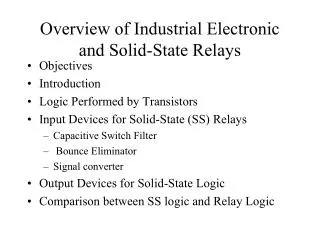
Industrial Electronic Features. Updated: November 2002. Industrial Features. The industrial features are classified as follows: Governor Features Throttle Features Equipment Integration Features System Diagnostics & Service Engine & Accessory Protection Operational Enhancements.

E N D
Industrial Electronic Features Updated: November 2002
Industrial Features • The industrial features are classified as follows: • Governor Features • Throttle Features • Equipment Integration Features • System Diagnostics & Service • Engine & Accessory Protection • Operational Enhancements
Governor Features • Governor Basics • Min/Max or Automotive Governor • All Speed or Variable Speed Governor • Auxiliary Speed • Tailshaft Governor • Pressure Governor • Hybrid Governor • High Speed Governor • Intermediate Speed Control Governor • Low Speed Governor • Engine Speed Cruise
Governor Basics • A governor is logic to control a certain functionality. • Engine Speed Governors: Governors like the Low Idle, High Idle & All Speed Governors & Intermediate Speed Control (PTO speeds) are “speed” governors & they control the engine to a certain engine speed. • Fueling Governors: Governors like Min-Max and Hybrid calculate fueling based on throttle position and engine speed. • Shaft Speed Governors: Tailshaft Governor (Auxiliary Governor) controls the speed of the engine to keep an output shaft at a constant speed. • Pressure Governors:Pressure Governor(Auxiliary Governor) controls the speed of the engine to maintain a constant pressure of an auxiliary pressure input.
Fueling Area in between the Low & High Idle Governor is generally Governed by Min-Max, All Speed Governor or Intermediate Speed Control Low Idle Governor High Idle Governor Engine Speed (RPM) Governor Basics
Fueling Droop High Idle Low Idle ASG Reference Point RPM Droop Basics • Droop is the change in engine speed over change in fueling or change in engine speed with change in load. • Droop % = (no_load_speed - full_load_speed) x 100 (full_load_speed )
Fueling Low Idle RPM Droop Basics • Isochronous Droop - Is a 0% droop where the engine RPM is maintained at a constant value over an available range of fueling irrespective of the increase or change in load.
Min/Max Governor (Automotive Governor) • What: Min/Max Governor controls fueling(torque) based on throttle percent and engine speed • How: • With the calibration, you can select the type of governor mode in which you wish to operate. • Why: This feature is used in applications with foot throttles & where large instantaneous change in loads are not experienced. • Benefits: • Improved driveability for applications which operate like on road vehicles (wheeled applications) • Applications Examples: Haul Trucks, Cranes, Cars
All Speed Governor (Variable Speed (VS) Governor) • What: Throttle position corresponds to an engine speed reference point. • How: • With a calibration, you can select what type of governor you would like for your specific application • Why: You would need this for applications that have hand throttles & where sudden & large changes in load is experienced. • Benefits: • Holds engine speed relatively constant when load varies. • Application Examples: Wheel Loader, Excavator, Ag Equipment, Multiple Applications
Auxiliary Speed Control - Tailshaft Governor • What:This features helps control the engine so as to maintain a desired tailshaft speed. • How: • This feature is activated by an operator switch . • The switch must go from an OFF to ON state to activate the feature. • The feature allows switching between Aux. Speed and All Speed Governor. • A desired shaft speed is requested by a potentiometer (throttle input). The ECM will control the engine speed to maintain the shaft speed. • Why: To control the speed of auxiliary equipment • Benefits: • This feature helps reduce installation cost by eliminating external devices to maintain tailshaft speed. • Application Examples: Rock Crusher, Ski Lift
Auxiliary Speed Control - Pressure Governor • What: A desired pressure is requested via throttle input & the ECM will control the engine speed to maintain the desired pressure. • How: • A desired pressure is requested by a potentiometer (throttle input). The ECM will control the engine speed to maintain constant pressure. • This feature is activated by an operator switch . • The switch must go from an OFF to ON state to activate the feature. • Why: Used to control air compressors. • Benefits: • Installation cost savings by eliminating additional or external pressure governor. • Application Examples: Air Compressor, Water Pumps or any other application where constant pressure is required.
Hybrid Governor • What: This feature enables the engine to run on pre-determined part throttle torque curves. • How: • This feature is implemented by calibrating throttle position dependent fueling limits for the all speed governor. • This feature can be enabled & disabled via a calibration. • Once enabled, this feature will automatically come into effect. • Why: This feature tries to accommodate for different driving techniques (operating speeds 2100RPM vs. 1800RPM) • Benefits: • Improved operator feel • Smoother & more efficient operation of equipment. • Improved fuel economy • Application Example: Ag Application, Hydraulic Excavator
New Installation Request*- Governor Selection *Note: All New Installation Request forms shown in this presentation are for Mid-Range engines unless other wise noted.
High Speed Governor • What: The high speed governor limits the engine RPM as selected by it’s breakpoint. • How: • This feature is calibratable by setting the desired high speed governor breakpoint. • The droop for the high speed governor is also a calibratable option.It can be set to have a percentage droop or it can be isochronous. • Why:This feature prevents the engine from overspeeding; it sets engine speed to within engine limits or may be set to protect machine/equipment. • Benefits: • Cost benefits by preventing engine/equipment damage due to overspeeding • Improved engine durability • Application Examples: All Applications
Governor Basics Isochronous Low Idle Speed High Speed Break Point IsochronousHigh Speed Fueling Low Idle Governor High Idle Governor Engine Speed (RPM)
Intermediate Speed Control(PTO Governor) • What: This is a fixed speed governor that provides the capability to choose up to 8 different engine speed set points • How: • 3 separate switch inputs & a resistor network for up to 5 points. • The 8 speed points are preset speed points in the calibration • The preset points can be adjusted with an inc/dec switch on the dash & can be changed by an operator. • Why: This feature is used to drive auxiliary equipment with precise engine speed control • Benefits: • Reduces cost of installation compared to mechanical engines • Make it simpler for operator to set speeds when desired. • Improves engine durability (operate at lower speeds) & fuel economy • Better control of desired speed • Application Examples: Feller Buncher, Garbage Truck
Low Speed Governor • What: This feature limits engine RPM above a minimum set point value for startup conditions. • How: • This feature is a calibratable feature with the capability to set the low idle engine RPM • Why:This feature prevents the engine from stalling when the operator’s foot is off the throttle • Benefits: • Improved engine performance at start-up & engine idle speed. • Quick response to load applications (eg.clutch engagement) • The droop increases operator awareness to increasing load. • Application Examples: All applications
Engine Speed Cruise • What: Engine speed is maintained at a speed selected by using the standard cruise switches. • How: • This feature can be enabled by calibration. • Why:Engine speed is adjusted with the throttle and then set and maintained automatically. • Benefits: • Allows engine speed to be set and maintained without the need for a vehicle speed sensor. • Application Examples: Ag Sprayers or any vehicle that needs to maintain its engine speed.
Throttle Features • Remote Throttle • Deceleration Throttle • Min Wins / Max Wins • Frequency Throttle • Industrial Default Throttle Values • Throttle Limp Home
Primary Throttle • What: This is the primary operator means for controlling engine speed or torque. • How: • The OEM will need to provide a potentiometer or switch to control throttle input. • The OEM provided potentiometer may include idle validation switches. • Via J1939 • Application Examples: Most Applications (ISC)
(Cab) (Remote) Remote Throttle • What: This is an alternate throttle input to remotely control the engine. • How: • This feature has an enable switch that activates the Remote Throttle & ignores the Primary Throttle. • The OEM will need to provide a potentiometer to control throttle input. • Via J1939 • Why: It is used in applications where remote control of the engine is required. • Benefits: • Installation cost reduction - no after market remote throttle controls needed. • Application Examples: Pavers, Asphalt Pavers, Chippers, Rock Crushers, Sprayers, Etc.
Min Wins / Max Wins • What:This feature can be set to choose the max throttle value between the Primary Throttle or the Remote Throttle or it can be set to chose the min throttle value. • How: • Once enabled via the calibration, the feature compares the primary throttle with the remote throttle to make choice of control. • Why:To modify equipment operation without changing the desired primary throttle position. • Benefits: • Improved equipment operation due to the ability to maneuver without changing primary throttle position. • Application Examples: Bulldozers, Front End Loaders.
Deceleration Throttle • What:This feature allows another throttle input to subtract from the primary set throttle value • How: • Once enabled via the calibration, the feature works in conjunction with the primary throttle. • OEM will have to provide wiring from appropriate pin & a potentiometer to provide the deceleration throttle input. • Why:This feature slows equipment operation without changing the desired primary throttle position.This feature works like an override decelerator • Benefits: • Improved equipment operation due to the ability to maneuver without changing primary throttle position. • Application Examples: Bulldozers, Tractors, Front End Loaders.
Frequency Throttle • What: This feature converts a frequency signal into a requested throttle percentage. • How: • The feature interprets a 0-5 volt frequency signal into a corresponding throttle value between the 0%-100% throttle • The frequency signal supplied must conform to the Cummins Engineering Standard #14118 • Idle validation is supported with this feature • Why: This feature provides flexibility to adapt to “non-standard” throttles used in the industrial & marine & mining markets.This also reads frequency input as opposed to an analog input. • Benefits: • Integration flexibility • A more accurate & robust throttle feature as it’s less dependent on a need for a highly accurate voltage reference. • Installed cost savings by eliminating the need for an external device to interface with the frequency throttle. • Application Examples: Marine, Electric Drive Haul Truck
Industrial Default Throttle Values • What: The Industrial Default Throttle determines the values of the throttle when certain throttle related systems errors become active. • How: • The feature separately sets the throttle to a value for high and low out of range errors. • Why:This feature will allow operator to generate some useful torque until the throttle is repaired. It is used when throttle limp home is not selected due to lack of the idle validation switch. May not be used when limp home is enabled. • Benefits: • Protects the equipment from undesirable engine condition due to loss of throttle signal. • Application Examples: All applications
New Installation Request - Default Throttle • Notes: • Industrial Throttle Default (OOR = Out of Range) (Leave Blank if Limp Home is required) • RPM Value should refer to maximum “no load” speed
Throttle Limp Home • What: This feature provides the capability to continue equipment operation after a throttle failure occurs. • How: • When throttle failure has occurs, throttle position will be calculated via the Idle Validation switches. • The feature will default to some calibratable fueling value to continue operation of equipment. • Why: This feature will allow operator to generate some useful torque until the throttle is repaired. • Benefits: • Reduces down time • A safety mode should throttle signal be lost to prevent engine run away. • Application Examples: All mobile applications with idle validation
Electronic Fan Control ON/OF PWM Signal PWM Dedicated Pin Output Switchable Torque Curves Switchable Droop Cold Start Aids Grid Heater Controls Controlled Ether Injection Speed Signal to Tachometer Multiple Unit Synchronization Switched Outputs Based on Sensed Parameters Oil Level Monitor J1587 Datalink J1939 Datalink Equipment Integration Features
Electronic Fan Control - On/Off • What: This feature provides a signal to turn ON or OFF a standard electronic fan clutch. • How: • When certain parameters like the engine coolant or intake manifold temperature reaches a predetermined limit, the fan clutch turns ON. • This feature can also be turned ON/OFF by a manual switch. • OEM needs to supply ground line from from the fan clutch to the engine . • Provide harness hook up on the OEM side. • Why: This feature helps maximize horse power to engine. • Benefits: • Reduced fuel consumption • Increases available horsepower in comparison to a constant ON fan • Application Examples: Any application which utilizes a clutched fan
Coolant Temp Sensor IMT, Fuel Temp (QSK19/45/60 only) OEM, Hydr Oil Temp Transient Condition Control Valve ECM o o o o o o o o o o o o o o o o o o o o o o o o o o o o o o o o o o o o o o o o o o o o o o o o o o o o o o o o o o o o o o o o o o o o o o o o o o o o o o o o PWM Electronic Fan Control - via PWM • What: This feature provides a Pulse Width Modulated (PWM) signal to control a variable speed fan clutch. • How: • The variable fan speed is controlled based on various engine and vehicle inputs. • An optimum PWM level is calculated based on the input sensor signals. • Why: This feature modulates fan speed as needed opposed to a constant speed fan. This feature helps optimize fan horse power loss. • Benefits: • Reduced fuel consumption • Lengthens belt life • Improved performance by limiting belt hop & slippage (via ramp ON/OFF) • Reduced fan noise • Application Examples: Most applications; Loaders, Haul truck
OEM fan switch. To pin 27 of 31 pin OEM connector. Open switch = 0% fan. Closed switch = 100% fan. Oil supply from main oil rifle Intake Manifold Temp Coolant Temp OEM temp signal return (0V -5V). To pin ‘J’ of 21 pin OEM connector. S270 Rockford Fan Clutch PWM Proportional Valve ECM OEM temp signal. To pin ‘K’ of 21 pin OEM connector. Ground Engine Mounted Bracket From Pin ‘11’ of 31 pin OEM connector. Oil return to sump To pin ‘F’ of 21 pin OEM connector. OEM pressure switch Fuel Temp Engine Speed Return to pin ‘X’ of 21 pin OEM connector. Cummins Scope of Supply QSKV ECM Fan Control - System Diagram
Transm. PWM Dedicated Pin Output • What: This feature provides a pulse width modulated (PWM) signal that can represent a number of engine parameters for OEM’s. • How: • The OEM will need an electronic control module to read/convert the PWM signal. • The PWM signal generated can be based on % throttle, engine speed, engine load (for midrange), engine torque at speed. This can be set up in the calibration. • Why: This feature provides an analog signal to be used by the equipment subsystems that need to be modulated as a function of engine load, engine speed, % throttle etc. Used in the absence of a datalink • Benefits • This feature provides an alternate method of controlling the engine & transmission • Maximizes utilization of transmission capabilities • Applications Examples: Transmission shift selectorfor potentially any application
New Installation Request - Dedicated PWM Output • DEDICATED PWM OUTPUT OPTIONSPWM Output Signal will provide: (Check one if desired)
T RPM Alternate Torque Curves • What:This feature allows the OEM to switch between the 100% throttle torque curve & up to two derated torque curves. • How: • This feature can be activated by the operator with a vehicle switch. • A 2 or 3 position switch can be used to switch between the 100% & the 2 additional torque curves. • Why: This feature is used when there is a need to limit engine torque output to protect drivelines, or to change the functional characteristics during a particular operating mode. • Benefits: • Optimizes performance based on operating characteristics of the equipment. • Operation cost savings by protecting equipment & components from damage. • Possible fuel savings • Application Examples: Loaders, Ag Equipment
Alternate Droop • What: This feature allows the droop characteristics to be changed for both the High Speed & All Speed Governor. The droop is expressed as a percentage. • How: • The droop & throttle feel is selected with an input from an operator switch. • A 2 or 3 position switch is used to select up to 3 droop options. • This feature can alter the reference point & droop for the High Speed Governor as well as reference point & droop(0% & 100% for the all speed governor. • Why: This feature improves equipment operation. • Benefits • This feature improves operator feel for applications with varying modes of operation. • Application Examples: Ag Applications & Graders
Cold Start Aid - Grid Heater • What: This feature controls a grid heater in the air intake manifold. • How: • A “Wait to Start” lamp controlled by the ECM advises the operator to pause after the key is turned ON for the grid heater to complete the preheat cycle before attempting to start the engine. • The OEM will have to supply relay(s) to interface with the grid heater. • Why: This feature serves to 1) preheat the intake air prior to cranking to improve cold starting & 2) to increase air temp. when engine temp. is low to reduce white smoke. • Benefits: • Installation simplicity due to the integrated grid heater & controls • Improved performance at starting & reduced white smoke • Application Examples: Any application