Download
1 / 89
970 likes | 1.3k Views
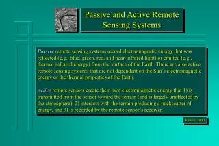
What is Sensing ?. Collect information about the world Sensor - an electrical/mechanical/chemical device that maps an environmental attribute to a quantitative measurement Each sensor is based on a transduction principle - conversion of energy from one form to another.

E N D
What is Sensing ? • Collect information about the world • Sensor - an electrical/mechanical/chemical device that maps an environmental attribute to a quantitative measurement • Each sensor is based on a transduction principle - conversion of energy from one form to another
Transduction to electronics • Thermistor: temperature-to-resistance • Electrochemical: chemistry-to-voltage • Photocurrent: light intensity-to-current • Pyroelectric: thermal radiation-to-voltage • Humidity: humidity-to-capacitance • Length (LVDT: Linear variable differential transformers) : position-to-inductance • Microphone: sound pressure-to-<anything>
Human sensing and organs • Vision: eyes (optics, light) • Hearing: ears (acoustics, sound) • Touch: skin (mechanics, heat) • Odor: nose (vapor-phase chemistry) • Taste: tongue (liquid-phase chemistry) Counterpart?
Extended ranges and modalities • Vision outside the RGB spectrum • Infrared Camera, see at night • Active vision • Radar and optical (laser) range measurement • Hearing outside the 20 Hz – 20 kHz range • Ultrasonic range measurement • Chemical analysis beyond taste and smell • Radiation: a, b, g-rays, neutrons, etc
Electromagnetic Spectrum Visible Spectrum 700 nm 400 nm
Gas Sensor Gyro Accelerometer Metal Detector Pendulum Resistive Tilt Sensors Piezo Bend Sensor Gieger-Muller Radiation Sensor Pyroelectric Detector UV Detector Resistive Bend Sensors CDS Cell Resistive Light Sensor Digital Infrared Ranging Pressure Switch Miniature Polaroid Sensor Limit Switch Touch Switch Mechanical Tilt Sensors IR Sensor w/lens IR Pin Diode Thyristor Magnetic Sensor Polaroid Sensor Board Hall Effect Magnetic Field Sensors Magnetic Reed Switch IR Reflection Sensor IR Amplifier Sensor IRDA Transceiver IR Modulator Receiver Radio Shack Remote Receiver Lite-On IR Remote Receiver Solar Cell Compass Compass Piezo Ultrasonic Transducers
Sensors used in robot navigation • Resistive sensors • bend sensors, potentiometer, resistive photocells, ... • Tactile sensors • contact switch, bumpers… • Infrared sensors • Reflective, proximity, distance sensors… • Ultrasonic Distance Sensor • Inertial Sensors (measure the second derivatives of position) • Accelerometer, Gyroscopes, • Orientation Sensors • Compass, Inclinometer • Laser range sensors • Vision • Global Positioning System
Classification of Sensors • Internal state (proprioception) v.s. external state (exteroceptive) • feedback of robot internal parameters, e.g. battery level, wheel position, joint angle, etc, • observation of environments, objects • Active v.s. non-active • emitting energy into the environment, e.g., radar, sonar • passively receive energy to make observation, e.g., camera • Contact v.s. non-contact • Visual v.s. non-visual • vision-based sensing, image processing, video camera
Robotic Sensor Classification • In general, robotic sensors can be divided into two classes: • Internal state sensors - device being used to measure the position, velocity and acceleration of the robot joint and/or end-effector. These devices are potentiometer, tachometers, synchros, resolvers, differential transformers, optical interrupters, optical encoders and accelerometer. ii. External state sensors– device being used to monitor the relationship between the robot kinematics and/or dynamics with its task, surrounding, or the objectbeing manipulated.
Sensor Selection/Sensing Taxonomy • There are many different types of robot sensors available and there are many different parameter measured by these sensors. • The application process, should be carried out in a top down manner, starting with task requirements, and going through several levels of analysis, eventually leading to the selection of a specific device. • A taxonomy for sensing to aid this process consists of five levels of refinement leading to sensor selection: • Specification of task requirements:eg localization, slippage detection, size confirmation, inspection, defect testing. • Choice of modality:eg,vision, force, tactile • Specification on sensor attributes:eg,output, complexity, discrete or continuous variable, imaging or non-imaging, local or global • Specification of operational parameters:eg size, accuracy, cost • Selection of mechanism:eg switching devices, inductive sensors, CCD vision imaging
Some tasks requirements features: • Insertion Monitoring • Assembly Verification • Detection of Reject Parts • Recognition of Part Types • Assembly Test Operations • Check Gripper/Tool Operation • Location & Orientation of Parts • Workspace Intrusion Detection • Check Correct Manipulation of Parts • Analysis of Spatial Relations Between Parts
Some typical sensor operational data: • Ultrasonics • Resistive Effects • Capacitive Efects • Piezo-Electric Effects • Visible Light Imaging • Photo-Electric & Infrared • Mechanical Switching • Inductive Effects • Thermal Effects • Hall Effect Primary physical mechanisms employed in sensors: Cost Range Accuracy Repeatability Power Requirements Output Signal Specification Processing Reuirements Sensitivity Reliability Weight Seze
SENSORS FOR INDUSTRIAL ROBOTS Proximity and Range Sensors Tactile Sensors Vision Sensors Miscellaneous Sensors
PROXIMITY & RANGE SENSORS I • It is a technique of detecting the presence or absence of an object with electronic noncontact sensors. • Typical application of proximity sensors includes: ש Object detection ש Collision avoidance ש Object verification & counting • Commonly available proximity sensors are: 1. Photoelectric/optical sensors 2. Inductive proximity sensors 3. Capacitive proximity sensors 4. Ultrasonic proximity sensors
Resistive Sensors • Bend Sensors • Resistance = 10k to 35k • As the strip is bent, resistance increases • Potentiometers • Can be used as position sensors for sliding mechanisms or rotating shafts • Easy to find, easy to mount • Light Sensor (Photocell) • Good for detecting direction/presence of light • Non-linear resistance • Slow response to light changes Resistive Bend Sensor Potentiometer Photocell R is small when brightly illuminated
Applications Sensor • Measure bend of a joint • Wall Following/Collision Detection • Weight Sensor Sensors Sensor
V + Binary Threshold - Inputs for Resistive Sensors Voltage divider: You have two resisters, one is fixed and the other varies, as well as a constant voltage V R1 Vsense R2 A/D converter micro Digital I/O Comparator: If voltage at + is greater than at -, digital high out
Infrared Sensors • Intensity based infrared • Reflective sensors • Easy to implement • susceptible to ambient light • Modulated Infrared • Proximity sensors • Requires modulated IR signal • Insensitive to ambient light • Infrared Ranging • Distance sensors • Short range distance measurement • Impervious to ambient light, color and reflectivity of object
Intensity Based Infrared Break-Beam sensor Reflective Sensor Increase in ambient light raises DC bias voltage • Easy to implement (few components) • Works very well in controlled environments • Sensitive to ambient light time voltage time
IR Reflective Sensors • Reflective Sensor: • Emitter IR LED + detector photodiode/phototransistor • Phototransistor: the more light reaching the phototransistor, the more current passes through it • A beam of light is reflected off a surface and into a detector • Light usually in infrared spectrum, IR light is invisible • Applications: • Object detection, • Line following, Wall tracking • Optical encoder (Break-Beam sensor) • Drawbacks: • Susceptible to ambient lighting • Provide sheath to insulate the device from outside lighting • Susceptible to reflectivity of objects • Susceptible to the distance between sensor and the object
Modulated Infrared • Modulation and Demodulation • Flashing a light source at a particular frequency • Demodulator is tuned to the specific frequency of light flashes. (32kHz~45kHz) • Flashes of light can be detected even if they are very week • Less susceptible to ambient lighting and reflectivity of objects • Used in most IR remote control units, proximity sensors Negative true logic: Detect = 0v No detect = 5v
amplifier bandpass filter integrator limiter demodulator comparator IR Proximity Sensors • Proximity Sensors: • Requires a modulated IR LED, a detector module with built-in modulation decoder • Current through the IR LED should be limited: adding a series resistor in LED driver circuit • Detection range: varies with different objects (shiny white card vs. dull black object) • Insensitive to ambient light • Applications: • Rough distance measurement • Obstacle avoidance • Wall following, line following
IR Distance Sensors • Basic principle of operation: • IR emitter + focusing lens + position-sensitive detector Modulated IR light Location of the spot on the detector corresponds to the distance to the target surface, Optics to covert horizontal distance to vertical distance
IR Distance Sensors • Sharp GP2D02 IR Ranger • Distance range: 10cm (4") ~ 80cm (30"). • Moderately reliable for distance measurement • Immune to ambient light • Impervious to color and reflectivity of object • Applications: distance measurement, wall following, …
Range Finder • Time of Flight • The measured pulses typically come form ultrasonic, RF and optical energy sources. • D = v * t • D = round-trip distance • v = speed of wave propagation • t = elapsed time • Sound = 0.3 meters/msec • RF/light = 0.3 meters / ns (Very difficult to measure short distances 1-100 meters)
Ultrasonic Sensors • Basic principle of operation: • Emit a quick burst of ultrasound (50kHz), (human hearing: 20Hz to 20kHz) • Measure the elapsed time until the receiver indicates that an echo is detected. • Determine how far away the nearest object is from the sensor • D = v * t • D = round-trip distance • v = speed of propagation(340 m/s) • t = elapsed time Bat, dolphin, …
Ultrasonic Sensors • Ranging is accurate but bearing has a 30 degree uncertainty. The object can be located anywhere in the arc. • Typical ranges are of the order of several centimeters to 30 meters. • Another problem is the propagation time. The ultrasonic signal will take 200 msec to travel 60 meters. ( 30 meters roundtrip @ 340 m/s )
Ultrasonic Sensors • Polaroid ultrasonic ranging system • It was developed for auto-focus of cameras. • Range: 6 inches to 35 feet Ultrasonic transducer Transducer Ringing: • transmitter + receiver @ 50 KHz • Residual vibrations or ringing may be interpreted as the echo signal • Blanking signal to block any return signals for the first 2.38ms after transmission Electronic board http://www.acroname.com/robotics/info/articles/sonar/sonar.html
Operation with Polaroid Ultrasonic • The Electronic board supplied has the following I/0 • INIT : trigger the sensor, ( 16 pulses are transmitted ) • BLANKING : goes high to avoid detection of own signal • ECHO : echo was detected. • BINH : goes high to end the blanking (reduce blanking time < 2.38 ms) • BLNK : to be generated if multiple echo is required t
Ultrasonic Sensors • Applications: • Distance Measurement • Mapping: Rotating proximity scans (maps the proximity of objects surrounding the robot) Scanning at an angle of 15º apart can achieve best results
Laser Ranger Finder • Range 2-500 meters • Resolution : 10 mm • Field of view : 100 - 180 degrees • Angular resolution : 0.25 degrees • Scan time : 13 - 40 msec. • These lasers are more immune to Dust and Fog http://www.sick.de/de/products/categories/safety/
TACTILE SENSORS • Tactile sensing includes any form of sensing which requires physical touching between the sensor and the object to be sense. • The need for touch or tactile sensors occurs in many robotic applications, from picking oranges to loading machines. Probably the most important application currently is the general problem of locating, identifying, and organizing parts that need to be assembled. • Tactile sensor system includes the capability to detect such things as: • Presence • Part shape, location, orientation, contour examination • Contact are pressure and pressure distribution • Force magnitude, location, and direction • Surface inspection : texture monitoring, joint checking, damage detection • Object classification : recognition, discrimination • Grasping : verification, error compensation (slip, position ,orientation) • Assembly monitoring
The major components of a tactile/touch sensor system are: • A touch surface • A transduction medium, which convert local forces or moments into electrical signals. • Structure • Control/interface
Method of Transduction Resistive • It is the transduction method in tactile sensor design which has received the most attention. It is concerned with the change in resistance of a conductive material under applied pressure. • This technique involves measuring the resistance either through or across the thickness of a conductive elastomer. Most elastomers are made from carbon- or silicon-doped rubber. Resistive Tactile Element – Resistance Measured Through The rubber
Advantages: • Wide dynamic range • Durability • Good overload tolerance • Compatibility with integrated circuitry, particularly VLSI. • Disadvantages: • Hysteresis in some designs. • Elastromer needs to be optimized for both mechanical and electrical properties. • Limited spatial resolution compared with vision sensors. • Larger numbers of wires may have to be brought away from the sensor. • Monotonic response but often not linear. Resistive Tactile Element – Resistance Measured Across the rubber
Piezoelectric & Pyroelectric Effects Method of Transduction • Piezoelectric effect is the generation of a voltage across a sensing element when pressure applied to it. The voltage generated is proportionally related to the applied pressure. No external voltage is required, and a continuous analogue output is available from such sensor. • A pyroelectric effect is the generation of a voltage when the sensing element is heated or cooled. • Polymeric materials with piezoelectric and pyroelectric properties are appropriate for use with sensors. Piezoelectric/Pyroelectric Effects Tactile element
Advantages: • Wide dynamic range • Durability • Good mechanical properties of piezoelectric from pyroelectric materials • Temperature as well as force sensing capabilities • Disadvantages: • Difficult of separating piezoelectric from pyroelectric effects • Inherently dynamic - output decay to zero for constant load • Difficult of scanning elements • Good solution are complex
CAPACITIVE TECHNIQUE Method of Transduction • Tactile sensors within this category are concerned with measuring capacitance, which made to vary under applied load. • The capacitance of a parallel plate capacitor depends upon the separation of the plates and their area, so that a sensor using an elastomeric separator between the plates provides compliance such that the capacitance will vary according to applied load.
Advantages: • Wide dynamic range • Linear response • Robust • Disadvantages: • Susceptible to noise • Some dielectrics are temperature sensitive • Capacitance decreases with physical size ultimately limiting spatial resolution.
Mechanical Transduction Method of Transduction • A Linear Potentiometer • Advantages: • Well known Technology • Good for probe application • Disadvantages: • Limited spatial resolution • Complex for array construction Mechanical Transducer A linear Potentiometer
Magnetic Transduction Methods • Sensors using magnetic transduction are divided into two basic categories: Groups together sensors which use mechanical movement to produce change in magnetic flux. • Advantages: • Wide dynamic range • Large displacements possible • Simple • Disadvantages: • Poor spatial resolution • Mechanical problems when sensing on slopes. Magnetic tactile Element
2. Concerns magnetoelastic materials which show a change in magnetic field when subjected to mechanical stress. • Advantages: • Wide dynamic range • Linear response • Low hysteresis • Robust • Disadvantages: • Susceptible to stray field and noise. • A.C. circuit required Magneto resistive tactile Element
Optical Transduction Methods Method of Transduction • Advantages: • Very high resolution • Compatible with vision sensing technology • No electrical interference problems • Processing electronics can be remote from sensor • Low cabling requirements • Disadvantages: • Dependence on elastomer in some designs – affects robustness • Some hysteresis Optical Tactile Element Pressure to light Transduction