Download
1 / 44
970 likes | 2.92k Views
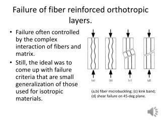
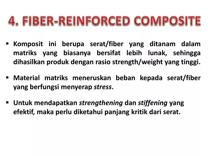
4. FIBER-REINFORCED COMPOSITE. Komposit ini berupa serat /fiber yang ditanam dalam matriks yang biasanya bersifat lebih lunak , sehingga dihasilkan produk dengan rasio strength/weight yang tinggi . Material matriks meneruskan beban kepada serat /fiber yang berfungsi menyerap stress .

E N D
4. FIBER-REINFORCED COMPOSITE • Kompositiniberupaserat/fiber yang ditanamdalammatriks yang biasanyabersifatlebihlunak, sehinggadihasilkanprodukdenganrasio strength/weight yang tinggi. • Material matriksmeneruskanbebankepadaserat/fiber yang berfungsimenyerapstress. • Untukmendapatkanstrengtheningdanstiffening yang efektif, makaperludiketahuipanjangkritikdariserat.
PENGARUH PANJANG SERAT • Sifatmekanik fiber-reinforced composite dipengaruhiolehsifatseratdanbagaimanabebanditeruskan/transmittedpadaserat. • Transmittance bebandipengaruhiolehbesarnyaikatan interfacial antaraseratdanmatriks. • Dibawah stress tertentu, ikatanantaraseratdanmatriksberakhirdiujungserat, sehinggapoladeformasimatriks yang terjadiadalahsepertigambardi slide berikut.
The deformation pattern in the matrix surrounding of fiber, subjected to an applied tensile
Adapanjangkritiktertentu yang diperlukan agar penguatanolehseratmenjadiefektif. • Panjangkritiklctergantungpada diameter seratddantensile strength*f , jugapadakekuatanikatanserat-matriksc, menurutpersamaanberikut: (3) Contoh: untukkombinasikacadanseratkarbon, lc = 1 mm (= 20 – 150 kali dimeternya)
Stress–positionprofiles when fiber length is equal to the critical length
Stress–positionprofiles when fiber length is greater than the critical length
Stress–positionprofiles when fiber length is less than the critical length
Kekuatankompositinidisebabkanolehikatanantaraseratpenguatdenganmatriks. • Rasiopanjang/diameter (disebutaspect ratio)dariseratpenguatakanmempengaruhisifat-sifatkomposit. • Semakinbesaraspect ratio, makasemakinkuatkomposit. Olehkarenaituuntukkompositkonstruksi, serat yang panjanglebihbaikdaripadaseratpendek. • Akantetapiseratpanjanglebihsulitdiproduksidaripadaseratpendek • Seratpendeklebihmudahdiaturdalammatriks, tetapiefekpenguatannyakurangbaikdibandingkandenganseratpanjang.
Olehkarenaituperluadanya trade-off antarajenisserat yang digunakandenganefekpenguatan yang diinginkan. • Jumlahseratjugaberpengaruhterhadapkekuatankomposit; semakinbanyakjumlahserat, makasemakinkuatkomposit yang dihasilkan. • Batas maksimumjumlahseratadalahsekitar 80% dari volume komposit. Jikajumlahserat > 80% makamatrikstidakdapatmenutupiseluruhseratdengansempurna. • Seratdenganl >> lc (normal: l > 15 lc) disebutkontinyu, sementaraSeratdenganl < 15 lcdisebutdiskontinyu. • Jikapanjangserat < lc, makakomposit yang dihasilkanpadadasarnyasamadenganparticulate composites.
PENGARUH ORIENTASI DAN KONSENTRASI SERAT • Susunanatauorientasiseratterhadapseratlainnya, konsentrasiserat, dankeseragamandistribusiakanmempengaruhikekuatandansifat-sifatlainnyadarifiber-reinforced composites. • Adaduaorientasi yang ekstrim: (i) sejajarteratur, dan (ii) acakseluruhnya. • Seratkontinyubiasanyasejajarteratur, sementaraseratdiskontinyudapatteraturatauacak.
Sifatmekanikdarikompositjenisinitergantungpada: • Perilaku stress-strain dariseratdanmatriks • Fraksi volume masing-masingkomponen • Arah stress ataubebanpada material komposit. Sifat-sifatkomposit yang memiliki fiber yang teratursangatanisotropic, yaitubesarnyanilaisifattergantungpadaarahpengukuran. Kita perhatikanperilaku stress-strain apabila stress dikena-kanterhadap material sejajardenganarahserat, yaituarah longitudinal, sepertiditunjukkanpadaGambar (a).
Ilustrasidarifiber-reinforced composites yang (a) kontinyudanteratur, (b) diskontinyudanteratur, and (c) diskontinyudanacak
Misalperilaku stress vs strain darifasa fiber danmatrikssebagaimanaditunjukkanpadagambardi slide berikut. Dalamhalini fiber bersifatsangatrapuh/brittle danmatriksbersifatcukupelastis/ductile. Padagambartersebut: *f : fracture strength in tension for fiber *m : fracture strength in tension for matrix *f : fracture strain in tension for fiber *m : fracture strain in tension for matrix
(a) Schematic stress–strain curves for brittle fiber and ductile matrix materials. Fracture stresses and strains for both materials are noted. (b) Schematic stress–strain curve for an aligned fiber-reinforced composite that is exposed to a uniaxial stress applied in the direction of alignment; curves for the fiber and matrix materials shown in part (a) are also superimposed.
Perilaku stress-strain dari material kompositditunjukkanpadagambar (b). Di daerah Stage I, fiber danmatriksmengalamideformasisecaraelastis; perilaku stress-strain biasanyaberupakurva linier. Matriksmengalamideformasiplastis, sedangkan fiber mengalami stretch elastis. Di daerah Stage II, hubunganantara stress dan strain hampir linier dengan slope yang lebihkecildaripada stage I. The onset of composite failure ditandaidengansaat fiber mulairusak, yaitupadasaat strain = *f. Padakondisiinikompositbelumrusakbenar, karena Tidaksemua fiber rusakpadasaat yang sama, Meskipunsebagian fiber telahrusak, tetapimatriksmasihutuhkarena*f <*m
Let us now consider the elastic behavior of a continuous and oriented fibrous composite that is loaded in the direction of fiber alignment. First, it is assumed that the fiber–matrix interfacial bond is very good, such that deformation of both matrix and fibers is the same (an isostrain situation). Under these conditions, the total load sustained by the composite Fc is equal to the sum of the loads carried by the matrix phase Fm and the fiber phase Ff, or (4)
From the definition of stress: Equation (4) can be written as: (5) dividing through by the total cross-sectional area of the composite, we have: (6) where Am/Ac and Af/Ac are the area fractions of the matrix and fiber phases, respectively.
If the composite, matrix, and fiber phase lengths are all equal, Am/Ac is equivalent to the volume fraction of the matrix, Vm, and Af/Ac and likewise for the fibers, Vf = Af/Ac. Eq.(6) now becomes: (7) The previous assumption of an isostrain state means that (8) and when each term in eq. (7) is divided by its respective strain (9)
Furthermore, if composite, matrix, and fiber deformations are all elastic, then the E’s being the moduli of elasticity for the respective phases. Substitution into eq. (6) yields an expression for the modulus of elasticity of a continuous and aligned fibrous composite in the direction of alignment (or longitudinal direction), as (10.a) (10.b)
Thus, Ecl is equal to the volume-fraction weighted average of the moduli of elasticity of the fiber and matrix phases. Other properties, including density, also have this dependence on volume fractions. for longitudinal loading, that the ratio of the load carried by the fibers to that carried by the matrix is (11)
EXAMPLE 1 A continuous and aligned glass fiber-reinforced composite consists of 40 vol% of glass fibers having a modulus of elasticity of 69 GPa and 60 vol% of a polyester resin that, when hardened, displays a modulus of 3.4 GPa. Compute the modulus of elasticity of this composite in the longitudinal direction. If the cross-sectional area is 250 mm2 and a stress of 50 MPa is applied in this longitudinal direction, compute the magnitude of the load carried by each of the fiber and matrix phases. Determine the strain that is sustained by each phase when the stress in part (b) is applied.
SOLUTION The modulus of elasticity of the composite is calculated using eq. (10.a): = 30 GPa To solve this portion of the problem, first find the ratio of fiber load to matrix load, using eq. (11); thus,
In addition, the total force sustained by the composite Fc may be computed from the applied stress and total composite cross-sectional area Ac according to this total load is just the sum of the loads carried by fiber and matrix phases; that is,
The stress for both fiber and matrix phases must first be calculated. Then, by using the elastic modulus for each (from part a), the strain values may be determined.
A continuous and oriented fiber composite may be loaded in the transverse direction; that is, the load is applied at a 90 angle to the direction of fiber alignment. For this situation the stress to which the composite as well as both phases are exposed is the same, or (12) This is termed an isostress state. Also, the strain or defor-mation of the entire composite is (13)
But since Substituting the above three to equations (13) yields: (14)
where is Ecl the modulus of elasticity in the transverse direction. Now, dividing through by yields (15) which reduces to (16)
EXAMPLE 2 Compute the elastic modulus of the composite material described in Example 1, but assume that the stress is applied perpendicular to the direction of fiber alignment. SOLUTION According to eq. (13):
We now consider the strength characteristics of continuous and aligned fiber-reinforced composites that are loaded in the longitudinal direction. Under these circumstances, strength is normally taken as the maximum stress on the stress–strain curve. Often this point corresponds to fiber fracture, and marks the onset of composite failure. Table 1 lists typical longitudinal tensile strength values for three common fibrous composites. Failure of this type of composite material is a relatively complex process, and several different failure modes are possible. The mode that operates for a specific composite will depend on fiber and matrix properties, and the nature and strength of the fiber–matrix interfacial bond.
Table 1. Typical Longitudinal and Transverse Tensile Strengths for Three Unidirectional Fiber-Reinforced Composites. The Fiber Content for Each Is Approximately 50 Vol%
If we assume that *f < *m, which is the usual case, then fibers will fail before the matrix. Once the fibers have fractured, the majority of the load that was borne by the fibers is now transferred to the matrix. This being the case, it is possible to adapt the expression for the stress on this type of composite, eq. (7), into the following expression for the longitudinal strength of the composite *cl (17) Here ’m is the stress in the matrix at fiber failure and, *fas previously, is the fiber tensile strength.
The strengths of continuous and unidirectional fibrous composites are highly anisotropic, and such composites are normally designed to be loaded along the high strength, longitudinal direction. However, during in-service applications transverse tensile loads may also be present. Under these circumstances, premature failure may result inasmuch as transverse strength is usually extremely low—it sometimes lies below the tensile strength of the matrix. Thus, in actual fact, the reinforcing effect of the fibers is a negative one. Typical transverse tensile strengths for three unidirectional composites are contained in Table 1.
Whereas longitudinal strength is dominated by fiber strength, a variety of factors will have a significant influence on the transverse strength; these factors include properties of both the fiber and matrix, the fiber–matrix bond strength, and the presence of voids. Measures that have been employed to improve the transverse strength of these composites usually involve modifying properties of the matrix.
Even though reinforcement efficiency is lower for dis-continuous than for continuous fibers, discontinuous and aligned fiber composites are becoming increasingly more important in the commercial market. Chopped glass fibers are used most extensively; carbon and aramid discontinuous fibers are also employed. These short fiber composites can be produced having moduli of elasticity and tensile strengths that approach 90% and 50%, respectively, of their continuous fiber counterparts.
For a discontinuous and aligned fiber composite having a uniform distribution of fibers and in which l > lc, the longitudinal strength (*cd) is given by the relationship: (18) where *f and ’m represent, respectively, the fracture strength of the fiber and the matrix when the composite fails. If l < lcthen the longitudinal strength is given by (19) where d is the fiber diameter and c is the smaller of either the fiber–matrix bond strength or the matrix shear yield strength.
Normally, when the fiber orientation is random, short and discontinuous fibers are used. Under these circumstances, a “rule-of-mixtures” expression for the elastic modulus similar to eq. (10.a) may be utilized, as follows: (20) In this expression, K is a fiber efficiency parameter that depends on and the Ef/Em ratio. Of course, its magnitude will be less than unity, usually in the range 0.1 to 0.6.
Thus, for random fiber reinforcement (as with oriented), the modulus increases in some proportion of the volume fraction of fiber. Table 2, which gives some of the mechanical properties of unreinforced and reinforced polycarbonates for dis-continuous and randomly oriented glass fibers, provides an idea of the magnitude of the reinforcement that is possible.
Table 2. Properties of Unreinforced and Reinforced Polycarbonates with Randomly Oriented Glass Fibers
Table 3. Reinforcement Efficiency of Fiber-Reinforced Composites for Several Fiber Orientations and at Various Directions of Stress Application