Download

1 / 8
80 likes | 185 Views
OMEN Nanoiwre* Supporting Document Limitation of the Tool at Large Gate Voltage. Sung Geun Kim**, Mathieu Luisier, Gerhard Klimeck Network for Computational Nanotechnology (NCN) Electrical and Computer Engineering *https://nanohub.org/resources/5359 **kim568@purdue.edu. Outline.

E N D
OMEN Nanoiwre* Supporting DocumentLimitation of the Tool at Large Gate Voltage Sung Geun Kim**, Mathieu Luisier, Gerhard Klimeck Network for Computational Nanotechnology (NCN) Electrical and Computer Engineering *https://nanohub.org/resources/5359 **kim568@purdue.edu
Outline Problem Statement What if a user wants to simulate a nanowire FET at large gate bias to obtain its on-current* using OMEN Nanowire? Then, the Id-Vg curve at high gate voltage is required. *On-current is defined as the drain current at Vg=Vdd where Vdd is positive supply voltage (http://en.wikipedia.org/wiki/Vcc). On-current is the measure of how fast the device can operate.
What happens at large Vgs? Problem in Id-Vg Characteristics Id : drain current , Vg : gate voltage Strange behavior of Id-Vg curve at large Vg. Circular Silicon Nanowire Dch* : 2nm Lch** : 15 nm χch† : 4.05eV φch‡ : 4.25eV *Dch : diameter of nanowire **Lch : channel length †χch : affinity of the channel material ‡φch : gate work function
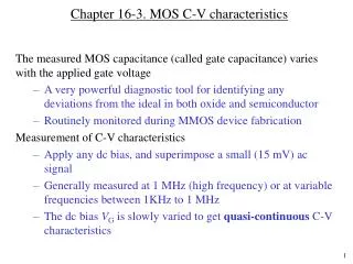
According to the bandstructure plot, problems occur at Vg=0.8V. Users need to look into the output log and input deck for a more detailed description of the simulation process Looking into the Device Behavior Bandstructure* *Explanations of the plot below can be found in the first time user guide of OMEN Nanowire Vg=0.8V Distorted conduction band edge
What is going on inside OMEN Nanowire? Output Log/Inputdeck Inputdeck is a part of output plots 1. Find the following script in the inputdeck 2. Look into “Output log”. You can scroll up and down to find where the problem happens Residue Vg = 0.8V, Vs = 0V, Vd=0.4V 3. Residue is larger than the criterion in the inputdeck whereby the iteration reached its maximum, 15. →Problem!! Poisson equation isn’t converged* n.b.) Poisson and Schrödinger equations are solved self-consistently to obtain the electron density and electrostatic potential in the nanowire. **”Converge” means that the residue of the solution of Poisson equation become smaller than the convergence criterion
Why isn’t it converged? Physical Meaning Vg=0.75V reflected electrons transmitted electrons At high gate voltage, the barrier height* in the channel becomes very small →The number of electrons reflected back at the barrier are too small. →The equilibrium in the source region** cannot be achieved. →Poisson equation cannot converge. *The barrier height is related to the workfunction of the gate and the affinity of the channel material **Equilibrium in the source : the number of electrons = the number of donors
So potential distortion occurs to achieve equilibrium at the source end. Raising the convergence criterion in such a situation does not help. The calculated drain current is not correct and has no meaning. This effect is inherent to ballistic transport and is not specific to OMEN. Why is the conduction band edge distorted? Forcing Equilibrium
Summary • The reason for the strange behavior of Id-Vg curve at high gate voltage is investigated • The high gate voltage causes barrier height to be lowered to some degree that the equilibrium in the source region cannot be achieved easily. • Poisson solver in OMEN attempts to distort(lower) the conduction band edge of the source end to achieve equilibrium. • →Drain current is changed or distorted due to this behavior. • The plotted drain current is not correct when Poisson equation does not converge. • Users need to be careful about the results at high gate voltages. • →Input deck and output log files should be carefully investigated