Download
1 / 72
720 likes | 871 Views
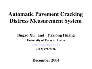
Detection and Measurement of Pavement Cracking . Bagas Prama Ananta. Overview. Background Aims The Proposed Method Tests and Results Conclusion Future Work. Background. Roads are a major asset in most countries To manage these assets, road authorities need:

E N D
Detection and Measurement of Pavement Cracking Bagas Prama Ananta
Overview • Background • Aims • The Proposed Method • Tests and Results • Conclusion • Future Work
Background • Roads are a major asset in most countries • To manage these assets, road authorities need: • Accurate, up-to-date information on the condition of their road network • Information on defects is vital to keeping a well maintain road network
Why do we do a Road Maintenance? • Early detection of defects in road surfaces helps: • maintenance to be performed before defects develop into more serious problems, such as potholes and pop-outs. • Thus, detection and measurement of pavement cracking: • Provide valuable information on the condition of a road network • Reduce maintenance cost • Create a better road network for people to use
Types of Cracks Transverse Cracking
Types of Cracks… Longitudinal Cracking
Types of Cracks Crocodile Cracking
Background… • The 1st maintenance process is the detection of defects • Once detected, defects can be analysed and a decision can be made as to what action needs to be taken
Present Method • Visual inspection • Two operators travel at 20 km/h • One as the driver, another to record the defect • Time consuming, costly and can be dangerous
Present Method… • An improved method • A video based system • Able to record the pavement up to 100 km/h • The recorded video is then inspected off-line at speed of 20 km/h
Project Aims • Proposing a method of semi-automated detection of cracking defects in the road pavement from video footage. • Advantages of a semi-automated system: • Faster • More reliable • More accurate
Challenges • Low resolution of the captured image • 768x576 pixels or 0.44 megapixels • Lossy compression is used • To make storage of the data practical • Highly variable lightning conditions • Potential false identification of cracks • Shadows, rail and tram tracks, other road objects
Challenges • Sample set provided by PureData, however the images were not suitable for testing. • Resolutions are too low • Most images are not sharp (i.e. a lot of blurry images) which result in noises • 1200x900 (~1mp) images are used to test the method
Commercial Implementation • Several companies offer solutions for monitoring road surface condition • Such solution are the CSIRO and Roadware crack detection systems • Due to the commercial nature, information on their operation is limited
CSIRO’s Road Crack Detection Vehicle • Comprised of mostly custom designed and manufactured hardware • The system is very expensive and requires specialised maintenance
CSIRO’s Road Crack Detection • Performs all data analysis in the field • No image data is kept • The only output is the road quality report • Leads to uncertainty with the accuracy of the results • Further manual inspection is needed to guarantee the results of the systems
Roadware’s Wisecrax • Performs all data analysis off-line • Dual video cameras record 1.5 m by 4 m sections of pavement • High intensity strobe lights produce consistent illumination of pavement images
Solution to Similar Problems • Crack Detection by the use of a laser based system • Work on this problem was commenced by a previous honours student (Timothy Evans). • A modified watershed algorithm was proposed • Difficulty in testing his algorithm • This project uses part of Tim’s method for detecting cracks • Sun et. al [2] proposed a new segmentation algorithm for detecting tiny objects • Edge detection, line growing and line cutting • Crack detection based on the “grid-cell” analsyis by Xu and Huang
The Proposed Method • To use image processing techniques to segment the cracking information. • Seed Selection • Line growing • Noise removal
Initial Detection or Seeding • Horizontal and Vertical Scan • Contrast Comparison • Combine seed
Profiles of Cracks, Lane Marks and Shadows • The challenge in crack detection is to differentiate between cracks and noises, where noises are: • Stone texture • Leaves, branches, etc • Lane Markings • Shadows • Analysing the different between the profiles between cracks and noise (lane marks and shadows) is useful for segmenting the crack from images.
Cracks on Shadows Cracks Cracks on shadows
Seed Selection – Contrast Comparison • A represents the current pixel. B and C are the candidate pixel for growing. • Calculate all the 4 directions: R=max(R(a), R(b), R(c), and R(d)). • If R > T, then the seed is validated else seed is discarded
Seed Selection - Combination • The proposed method of seed selection • The combination of Horizontal & Vertical and Contrast comparison • More accurate
Line Growing – Watershed transformation current pixel • Start from the current pixel • Mark pixels that are similar to the current pixel as a potential crack seed
Noise Removal • Flooded points must not be too close with each other to the extent the area is overcrowded • A crack will generally have a certain width • A crack will generally not be an isolated pixel