Download
1 / 39
390 likes | 511 Views
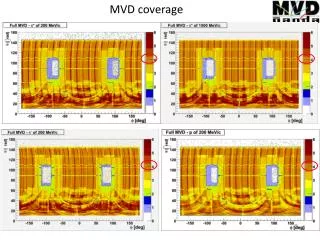
MVD Internal Review 28-Jan-2001 John P. Sullivan. Outline. Technical status of MVD hardware (John) Technical status of MVD software (Hubert) Steps needed to install and full MVD (John) Our commitment for operations of MVD (John) Physics plan with current MVD data (Hubert)

E N D
MVD Internal Review 28-Jan-2001 John P. Sullivan
Outline Technical status of MVD hardware (John) Technical status of MVD software (Hubert) Steps needed to install and full MVD (John) Our commitment for operations of MVD (John) Physics plan with current MVD data (Hubert) Physics plan with next run's MVD data (Hubert) Personnel needs and schedule of those needs (John) Budget (John) Outstanding issues (John)
Technical status of MVD hardware In approximate order of importance: • cooling lines • poor S/N • pedestal drift • readout problems in DCIM boards • glink locks • physical sagging The next slides explain these problems
Repair cooling tubes The cooling tubes carry water to cool voltage regulators collected on the motherboards (diagram at right). Brass fittings connect to them (below).
Repair cooling tubes (continued) The problem: “Galvanic corrosion” where the brass fittings touched the Al tubes. Holes created when disconnecting the fittings. The solution: Disassemble MVD, remove Al tubes, glue on Cu tubes. It is not conceptually hard. It will take~2 person weeks to do this. In 1/1 previous tests, the tube came off the motherboard without problems. Summary: We must fix this, but we know how.
MVD readout system A large rack in the IR The line between MVD and DAQ group responsibilities
Summary of problems in data 81 MCMs installed 61 MCM being read out 13 MCMs with good resolution
Good vs. “Poor” packet (1d) Good: Poor:
Packet ADC sum vs. BBC ADC sum Good: slope= 2.57 Poor: slope= 0.26
What do we know about the poor signal/noise problem? 1) The problem is in the signal 2) It is intermittent in some packets Possible causes:1) problem with bias voltage 2) level-1 timing wrong in some MCMs 3) preamplifiers "hit the rail" and are not reset often enough There are arguments for an against each of these possibilities. The real problem may be some combination of these and other problems.
Problem with bias voltage? The problem does not seem to be no bias to the MCMs with poor signal/noise. One detector will not hold the bias voltage. For this detector, the slope of the MCM ADC sum vs. BBC ADC sum is ~20 lower than an MCM with “poor signal/noise”:
Problem with bias voltage ? (continued) It seems that at least part of the bias voltage is reaching the assemblies which have poor signal to noise. Perhaps they are under-biased? There are problems in the bias distribution: ~3 bias channels trip even though there is no detector connected to them. The bias voltage distribution can be tested easily, we just need time and access to the MVD. My guess is that this is not the main problem. One reason is that the problem is intermittent for some packets. Another guess: ~6/81 MCMs have problems with bias V.
Level-1 delay problem? During DCIM tests, I noticed that some packets in a single event reported beam clock N and others N+1. It seemed reproducible. My suspicion is/was a problem in the timing of the level-1 trigger vs. the beam clock on our MCMs. The GTM can adjust the phase of these signals, but I am not sure that this phase difference is trasnsmitted through our TCIM. It is possible that the level-1 timing we use caused the clock and level-1 signals to arrive ~simultaneously at the MCM. The "Address List Manager" (an FPGA on the MCM) counts backwards 45 clocks to pick the pair of AMU cells for the "pre" and "post" samples. Are all ALMs consistent in counting recently arrived beam clock signals?
Level-1 delay problem? (continued) The problems with this explanation are: 1) Examinations of the level-1 delay curves for different packets (by Sangsu and myself independently) did not find any example consistent with these suspicions. 2) In the real data ~all packets have different beam clock numbers (i.e. not N and N+1). This is probably because of the order various arcnet and mode bits commands are sent to the different MCMs. Some arcnet commands reset the beam clock number, but can’t be sent to all MCMs simultaneously. Even if the consistency of the level-1 delay this is not the main problem, we need to understand it better. We also need to work on the order of the arcnet and mode bit reset commands -- to understand event numbers.
Do preamps “hit the rail”? MCM reset and preamp signals for various injected charges:
Do preamps “the the rail”? (continued) • The rising edge, marked by the arrow, is a “hit”. The preamp needs to be reset occasionally. This is done via a mode bit command through the GTM. • The details of the pulse shape are set via serial controls. The “Vfb” DAC can be set to give the behavior seen in the sample or to pull the signal back down to baseline. • If the preamp signal “hits the rail”, further hits on that channels cause no change in the preamp output. The “post” - “pre” difference is digitized, but it will be zero. • We took data runs Vfb changed from 3.0 V to 2.5 V, but have not examined the data to see if it helped.
Two Pedestal Problems Pedestals depend on AMU cell # Pedestals drift: (horizontal axis represents runs taken over ~10 days) Both are problems for zero suppression.
Problem with AMU cell dependent pedestal correction in pipelined mode
Pedestal drift -- AMU dependence too ADC value vs. AMU cell #, run 26557: ADC value vs. AMU cell #, run 27386
AMU dependence -- What do we know? The pedestal position depends on AMU cell number. The dependence varies with run number. The AMU cell number dependence is seen in other subsystems (e.g. EMCAL), but at roughly 1/10 of this level. We can calibrate the problem away (corrected in DCMs), but the algorithm is probably impractical in pipelined mode. We are unsure of the time scale of the shifts, but it seems long -- we did calibrations to correct this once per day.
Pedestal drift -- What do we know? We saw pedestal drift in Si+MCM system on the bench: ~15 chan/2.5 hours. Fastest shortly after turning the system on. On bench, apparently no shift without Si detector attached. We are unsure of the time scale of the shifts but there appears to be slow (~ hours) drift and more sudden shifts (<few minutes). Pedestals moved down ~25-50 channels when the beam was dumped in the PHENIX IR during an attempt to set level-1 timing. Pedestals slowly returned to original value after ~ 30 minutes. In the recent run, we did many calibrations to keep zero-suppression up-to-date. This annoys our collaborators.
Pedestal widths The pedestal width depends on the length of the cable connecting the Silicon detector and the MCM: far Close to beam pipe
What will we do about pedestal problems? Add shielding around cables from detector to MCM -- should help with pedestal width at least. More benchtop studies in SM-218. Tests with ~complete setup at BNL. Try to get help from ORNL engineers and Glenn Young.
Readout problems in DCIM boards There were various problems which are probably simple to fix but hard to find (e.g. broken or shorted traces). These problems prevented ~6/81 of our MCMs from being read out. 10/81 packets are returned with bad formats, these may also be easy to fix, but will take time to diagnose. We used the best 20 out of 36 boards. We need 24 boards for the next run. Guestimated time for this: 2 months for a person with electronics skills, patience, and good eyes.
Glink locks In the first run, this kept us from running with the rest of PHENIX. A series of problems related to grounding, termination of the VME backplane, and parts being used outside their specifications caused this problem. The current situation is drastically improved, but could be better. The typical time between failures improved from minutes to days. The solution is probably additional modifications in grounding. 2/81 MCMs (in sme cases 4/81) were no being read out due to Glink problems. But, there’s a storm on the horizon ...
A Glink storm on the horizon In the MVD barrel, channels 1-2 correspond to the ends. In the recent run, the ends of the barrel we not populated. Therefore, we could ignore the fact that channels 1-2 did not work on most DCIM boards.
Problem in DCIM channels 1-2 Of the DCIMs we bench tested, 46% = 16/35 had channels 1-2 “bad” (8 Glink problems) 29% = 10/35 had channels 3-4 “bad” (0 Glink problems) 29% = 10/35 had channels 5-6 “bad” (2 Glink problems) Using only DCIMs which passed QA tests above, we still found more problems in chan 1-2 than in the others. Of those boards used in the run, we found some problem in 60% = 6/10 cases for channels 1-2 23% = 7/31 cases for channels 3-4 20% = 8/40 cases for channels 5-6
Glink problems -- summary The previous slide may be too pessimistic -- it does not taken into account repairs, which happened to the “important” channels (3-6) more often than 1-2. We also fixed the TCIMs after everything was installed and after the jumpers used in the DCIM clock circuit were adjusted for each board. Readjusting these jumpers and further improvements in grounding could easily fix many of these problems. Glink lock problems were not a serious problem in the recent run.
Physical sagging Side view: MVD sags down in the middle ~ 5mm (exaggerated in this sketch). We would like to reduce this. Top view: MVD bows out in the middle too (also exaggerated in sketch). We would like to reduce this too.
Steps needed to complete installation Diagnosis and repair of problems in existing system: ~7 person months Repair cooling tubes (already discussed): ~1/2 person month Build and test additional detectors: ~3.5 person months Assemble, install, test completed system: ~2 person months Optional but important: improve ease of operation: ~6 person months Total: ~18 person months
Diagnosis and repair of existing system • The problems were described earlier. • We can do some tests on the bench in SM-218 • ~2/3 of the work needs to be done at BNL because • a lot of equipment in involved • it some combination of large/fragile/expensive/unique • some problems are “system-level”, can’t be tested in pieces • We can bench test ~ 1/2 of system at BNL (with a prototype LVPS). This is complicated by the cooling problem -- 1/2 of each 1/2 (1/4 of total) has a hole in the cooling. If we fix this first, we need to unstack and stack the MVD twice (~1-2 weeks of extra work)
Diagnosis and repair of existing system (continued) • We are trying to get help from ORNL (where most of the components were designed). ~Few weeks of help is available, more is contingent on funding help from DOE. • We do not have any construction funds left, except the funds committed to MCM purchase (capital equipment) • We will probably get some help from Yonsei. • We asked for help from Japanese (Enyo) -- The initial response was not encouraging, but not “no”.
Our commitment to MVD operations # FTE’s from LANL stationed at BNL = 0 No Allan for the next run Hope for help from Yonsei Someone has to carry the beeper 24hrs/7 days -- if it is only Hubert and I, that means we each need to be on travel a minimum of 1/2 time during the run. Not realistic.
Personnel needs and schedule of those needs Estimated hardware effort ~18 person months. We have ~8 months to do it. Want to keep Allan on analysis full time. We have max ~ 6 months of my time and ~ 8 months of Hubert’s time. Maybe ~1 month each from Yonsei and ORNL and we are still short by at least 2 person months with no analysis work from Hubert or me. We do not seem to have enough people to do the work. Enyo? PHENIX?
Budget Summary (CE only) Currently, we have about 61 K$ remaining (Z950). Of this: 46 K$ committed to Lockheed-Martin for MCM production 11 K$ needed for wirebonding and surface mounting 4 K$ left over Summary of spending in FY00-02:
Outstanding issues Staffing level. Who's at BNL for all the big tests? A lot a travel by a few people. We will have a problem in next run if we don’t get someone in residence at BNL.
Breakdown of FY00-02 spending K$, broken down into categories and program codes FY00 FY01 FY02
Breakdown of readout problems # MCMs problem probability we Solution estimated time to understand cause known? solve problem _______ _______ ______________ _______ __________ 27 poor 0.5 maybe weeks to months signal/noise 15 very poor 0.5 maybe weeks to months signal/noise 6 Readout OK, 0.2 probably weeks to months but no signal 10 no packet 0 Don't weeks to months or bad format know 5 stuck bit 0.9 Yes 2-3 weeks 2 Glink 0.9 Yes 1-5 days 1 bias trips 0.5 not sure 1 week?? 1 alternate data 0.9 Yes 1 hour words missing