Download
1 / 46
530 likes | 1k Views
Non-crystalline materials and other things. By the end of this section you should: know the difference between crystalline and amorphous solids and some applications for the latter understand how the different states affect the X-ray patterns

E N D
Non-crystalline materials and other things By the end of this section you should: • know the difference between crystalline and amorphous solids and some applications for the latter • understand how the different states affect the X-ray patterns • be able to show the Ewald sphere construction for an amorphous solid • be aware of different types of mesophases • know the background to photonic crystals
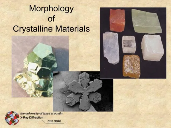
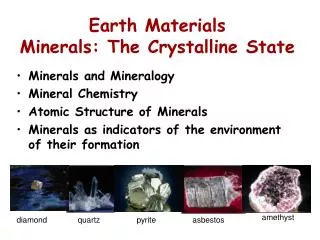
Amorphous Solids So far we have discussed crystalline solids. Many solids are not crystalline - i.e. have no long range order. They can be thought of as “solid liquids”
Amorphous Solids The arrangement in an amorphous solid is not completely random: 1) Coordination of atoms satisfied (?) 2) Bond lengths sensible 3) Each atom excludes others from the space it occupies. represented by radial distribution function, g(r) * g(r) is probability of finding an atom at a distance between r and r+r from centre of a reference atom * Sometimes known as pair distribution function
Radial Distribution Function Take a reference atoms with radius a g(r) = 0 for r<a g(r) 1 for large r At intermediate distances, g(r) oscillates around unity - short range order. From any central atoms, the nearest neighbours tend to have a certain pattern - though not so rigidly as in a crystal SiO4 - angles tend to 109.5º but are not exact
Radial Distribution Function As we move out, the pattern becomes more and more varied until we reach complete disorder X-ray diffraction can still give information on the structure. X-rays scattered from atoms (not planes) and interference effects will occur. We use angle , though this does not relate to any lattice plane as in Bragg’s law.
Radial Distribution Function Scattered intensity depends on modulus - not direction - of K for an amorphous material. This means that diffraction patterns have circular symmetry rather than spots.
Interference Function The interference function (i.e. “scattering factor” for amorphous materials) S(K) is given by: sinc Kr dr where n is the no. of atoms per unit volume and sinc = sin / S(K) is a Fourier transform of {g(r)-1} and sinc Kr dK
Measurements We can measure the intensity, I(K), which (we assume) is directly related to S(K). Thus g(r) can be calculated from the interference effects in the (circular) diffraction pattern, and hence interatomic distances can be estimated. e.g. taking a radial cut from the centre of the pattern:
Measurements Assignments made on expected distances between atoms As we get further out, becomes less “ideal” due to increased disorder
“Solid Liquids” Diffraction patterns of an amorphous solid and a liquid of the same composition are very similar: The average structures are more or less the same. Short range order less well developed in liquid (peaks not so well defined)
a2 a3 a 2a 3a RDF in crystals We can also calculate this for a perfect crystal Polonium, a = 3.359 Å This can allow analysis of “not so perfect” crystals – disorder “Total diffraction”
Ewald Sphere for amorphous solids From previously: i.e. scattering depends only on modulus of K. So we have a reciprocal “sphere” of radius |K| intersecting with the Ewald sphere: This gives a circle where they intersect = diffraction pattern. (circle perp. to page)
Back to EXAFS • The Fourier transform of the EXAFS spectrum is also a radial distribution function Intensity vs R (radius from central atom)
Volume liquid Glass transition VF glass melting crystal Temperature Tg Tm Free volume Free volume (VF) defined as: SV of glass/liquid - SV of corresponding crystal SV = Volume per unit mass
Amorphous silicon • Amorphous materials often not good conductors – pathways blocked • Crystalline silicon – diamond structure, 4-fold coordination, regular (corner-sharing) tetrahedra • Amorphous silicon – mostly 4-fold coordination, fairly regular tetrahedra BUT… • …not all atoms 4-fold coordinated • …“dangling bonds” Can be terminated by H atoms kypros.physics.uoc.gr/resproj.htm
Uses • Method of production means it can be deposited over large areas – thin films, flexible substrates • Photovoltaics – e.g. solar cells Energy conversion not so efficient as crystalline Si, but more energy efficient to produce
Photovoltaics • Instead of heat, light causes electron/hole pairs • Cell made of pn junction - photons absorbed in p-layer. • p-layer is tuned to the type of light - absorbs as many photons as possible • move to n-layer and out to circuit. http://solarcellstringer.com/ http://www.nrel.gov/data/pix/Jpegs/07786.jpg
Mesophases Normally a solid melts to give a liquid. In some cases, an intermediate state exists called the mesophase (middle). Substances with a mesophase are called liquid crystals
Crystal 145.5 °C LC 178.5°CI Friedrich Reinitzer (1857-1927) Liquid Crystals and Mesophases Cholesteryl benzoate Thanks to Toby Donaldson
Calamitic liquid crystals Discotic liquid crystals What types of molecules show liquid crystalline behaviour? • Anisometric molecular shape Thanks to Toby Donaldson
Polarised light microscopy Mostly now used in geology Gases, liquids, unstressed glasses and cubic crystals are all isotropic One refractive index – same optical properties in all directions Otto Lehmann (1855-1922) Most (90%) solids are anisotropic and their optical properties vary depending on direction. Birefringent Lysozyme crystals viewed by polarised light microscopy http://www.ph.ed.ac.uk/~pbeales/research.html
Isotropic Liquid crystalline cholesteric Crystalline Polarised light microscopy Thanks to Toby Donaldson
Mesophases If we increase temperature, we can see how the disordering occurs:
Mesophases - more detail (a) smectic phase - from the Greek for soap, smegma A C Layers are preserved, but order between and within layers is lost
Smectic Thanks to Toby Donaldson
Mesophases - more detail (b) nematic phase - from the Greek for thread, nemos Layers are lost, but the molecules remain aligned If we looked at this end on, it would look like a liquid
Nematic Phase, N Thanks to Toby Donaldson
Mesophases - XRD Example - mix of powder (circles) and ordering (arcs)
LCDs • LCs sandwiched between two cross polarisers • “twist” in LC allows light to pass through • Applied voltage removes twist and light no longer passes through http://www.geocities.com/Omegaman_UK/lcd.html http://www.edinformatics.com/inventions_inventors/lcd.htm
Photonic Crystals 1887: Lord Rayleigh noted Bragg Diffraction in 1-D Photonic Crystals 1987: Eli Yablonovitch: “Inhibited spontaneous emission in solid state physics and electronics” Physical Review Letters, 58, 2059, 1987 Sajeev John:“Strong localization of photons in certain disordered dielectric super lattices” Physical Review Letters, 58, 2486, 1987
1887 1987 1 - D 2 - D 3 - D p e r i o d i c i n p e r i o d i c i n p e r i o d i c i n o n e d i r e c t i o n t w o d i r e c t i o n s t h r e e d i r e c t i o n s Basics of photonics • Periodic structures with alternating refractive index Photonic band gap analogous to electronic band gap Weakly interacting bosons vs strongly interacting fermions http://ab-initio.mit.edu/photons/tutorial/ - S.G Johnston
Bragg’s Law – wider applications This is a general truth for any 3-d array. If we imagine the “atoms” as larger spheres, then: d becomes larger becomes larger – visible light This is the basis for photonic crystals n = 2d sin Opal (SiO2.nH2O) A fossilised bone! Silica spheres 150-300 nm in diameter – ccp/hcp http://www.mindat.org/gallery.php?min=3004
Bragg’s Law – wider applications We replace the d-spacing, from Bragg’s law, with the “optical thickness” nrd where nr is the refractive index (e.g. of the silica in opal) n = 2nrd sin nr is ~1.45 in opal so n = 2.9 d sin This gives max = 2.9 d for normal incidence
2r r Geometry of packed spheres If we assume the spheres “close pack”, then we can calculate d: sin 60 = d/2r d = 1.73 r max = 2.9 d So max = 5r (approx.) for normal incidence We now need to manipulate d!!
Photonic band gap From above: max = 2nrd at this , no light propagates And from de Broglie E = hc/ So in photonic crystals, we define the photonic band gap:
Photonics – in nature J. Zi et al, Proc. Nat. Acad. Sci. USA, 100, 12576 (2003); Blau, Physics Today 57, 18 (2004) http://newton.ex.ac.uk/research/
d Artificial Photonics Massive research area (esp. in Scotland!) Control areas of differing refractive index, e.g.
The first experiment An array of small holes 1mm apart were drilled into a piece of material which had refractive index 3.6. Calculate the wavelength of light “trapped” by this material • max = 2nrd • = 2 x 3.6 x 0.001 • = 7.2 x 10⁻³ m • Microwaves
Woodpile crystal [] “Logs” of Si 1.2 m wide K. Ho et al., Solid State Comm.89, 413 (1994) H. S. Sözüer et al., J. Mod. Opt.41, 231 (1994) http://www.sandia.gov/media/photonic.htm
“Artificial” photonic crystals S. G. Johnson et al., Nature. 429, 538 (2004) From amorphous silicon – 3D, 1.3 – 1.5 m T. Baba et al, Yokohama National University
Artificial Opal D. Norris, University of Minnesota: http://www.cems.umn.edu/research/norris/index.html
Inverse Opal Templating to produce… Yurii A. Vlasov, Xiang-Zheng Bo, James C. Sturm & David J. Norris., Nature 414, 289-293 (2001)
Inverse Opal • Silica spheres with a refractive index of 1.45 • ~ 1.3 m Q: Calculate d (and hence the radius of the spheres) from this information.
Uses From: K Inoue & K. Ohtaka: “Photonic crystals” ( Springer, NewYork,2003).
Summary • Amorphous materials show short range order and have have various applications e.g. in photovoltaics • X-ray interference effects still occur, leading to circular diffraction patterns which relate to g(r), the radial distribution function and the scattered X-ray intensity depends on the modulus of the scattering vector, K • States intermediate between crystalline and liquid exist - mesophases - such as nematic and smectic • These have wide applications, an example being LCDs • Extension of Bragg’s law to a different scale length leads us to consider photonic crystals