Download
1 / 44
470 likes | 677 Views
Two-Stage Dynamic Uplink Channel and Slot Assignment for GPRS. Author: Ying-Dar Lin, Yu-Ching Hsu, Mei-Yan Chiang Reporter: Chen-Nien Tsai. Outline. GPRS Background Introduction Two-Stage Dynamic Channel and Slot Assignment Results Summary. GPRS Background.

E N D
Two-Stage Dynamic Uplink Channel and Slot Assignment for GPRS Author: Ying-Dar Lin, Yu-Ching Hsu, Mei-Yan Chiang Reporter: Chen-Nien Tsai
Outline • GPRS Background • Introduction • Two-Stage Dynamic Channel and Slot Assignment • Results • Summary
GPRS Background • GPRS Introduction • GPRS Network Architecture • GPRS Air Interface • GPRS Logical Channels • Mapping Logical Channels to Physical Channels • Packet Data Transfer Operations
GPRS Introduction • GPRS: • Stands for General (or generic) Packet Radio Services • developed by European Telecommunication Standard Institute (ETSI) • is one of the standards of Global System for Mobile communications (GSM) Phase 2+ • is designed as a packet switching system
GPRS Network Architecture • It fits in with the existing GSM PLMN • Two new network elements • Serving GPRS Support Node (SGSN) • Gateway GPRS Support Node (GGSN) • Many new interfaces • Gb, Gi, Gn, etc.
GPRS Air Interface (1/3) • GPRS uses the existing GSM resources. • GPRS uses a two-dimensional access scheme (FDMA and TDMA). • Total 25 MHz bandwidth • 125 carrier frequencies of 200 kHz bandwidth • GPRS users will share the same TDMA frame with GSM voice users. • GPRS air interface will dynamically allocate resources (timeslots).
GPRS Air Interface (2/3) • TDMA Frame • 8 timeslots • Period = 4.615 ms
GPRS Logical Channels PDCH is the generic name for the physical channel allocated to carry packet logical channels
Mapping Logical Channels to Physical Channels (1/3) • Logical channels are carried on physical channels. • Multiple logical channels can be mapped onto the same physical channels. • Three possible combinations: • PBCCH+PCCCH+PDTCH+PACCH+PTCCH • PCCCH+PDTCH+PACCH+PTCCH • PDTCH+PACCH+PTCCH
Packet Data Transfer Operations • Before data can transfer • GPRS Attachment • PDP (Packet Data Protocol) context activation. • After these two steps, the mobile can access the network, request resources, and send data.
Uplink Packet Data Transfer • Request resources
Uplink Packet Data Transfer • Fixed radio block allocation • According to bit map
Uplink Packet Data Transfer • Dynamic radio block allocation • USF (Uplink State Flag) is attributed to each MS.
Outline • GPRS Background • Introduction • Two-Stage Dynamic Channel and Slot Assignment • Results • Summary
Introduction • Two-stage assignment • Stage-1: BS assigns several PDCHs to an MS. • Stage-2: BS selects one of the multiplexed MSs in a PDCH to use the radio resource. • Objective of this paper • Load balance in stage-1 • Good prediction in stage-2
Outline • GPRS Background • Introduction • Two-Stage Dynamic Channel and Slot Assignment • Results • Summary
Two-Stage Dynamic Channel and Slot Assignment • Stage 1 • Multiple PDCHs with the corresponding USFs are assigned to an MS. • Stage 2 • To utilize the radio resource, the BS has to predict who has data to send and the assign the following time slot to that MS.
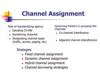
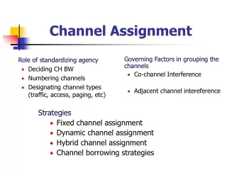
Stage-1 Channel Assignment • After receiving the Packet Channel Request, BS must decide the number of as well as which specific PDCHs to be assigned to the MS. • Deciding which PDCHs to assign is more critical. (load balance) • Two load measurement methods • Number of Assigned Flow • Effective transmission over last cycle
Number of Assigned Flow (NoAF) • The number of multiplexed MSs within a PDCH is chosen as the load measurement metric. • This scheme can be considered a frequency-wise and PDCH-wise balance.
Effective Transmission over Last Cycle (EToLC) • The load metric employed by EToLC is defined as the number of transmissions occurred during the previous PRR (Pure Round-Robin) cycle.
Stage-2 Slot Assignment • The BS has to predict who has data to send. • If the selected MS has no data impending, the slot is wasted. • Three schemes are considered: • Pure Round-Robin • Round-Robin with Linearly-Accumulated Adjustment • Optimal
Pure Round-Robin (PRR) • Each multiplexed MS in a PDCH is round-robined to use the uplink channel. • All MSs are assumed having impending data to send. • A PRR cycle equals the number of MSs multiplexed in this PDCH. • The highest mis-selection rate.
Round-Robin with Linearly-Accumulated Adjustment (RRLAA) • Basis principle • to reduce the transmission chance for the MSs that failed to utilize the last assigned slot, and increase the chance for those who had. • For RRLAA, a Penalty cycle and a Reward cycle are defined and appear alternately.
Penalty Cycle (1/2) • A Penalty cycle is derived from PRR cycle by skipping MSs who waste their last assigned timeslots in Penalty cycles. • An MS will be skipped in n successive penalty cycles when it wastes n successive assigned timeslots in Penalty cycles. • When the MS begins to send packets, the penalty accumulation is reset.
Penalty Cycle (2/2) M: number of multiplexed MS in a PDCH
Reward Cycle (1/2) • An MS is authorized to transmit during the following Reward cycle if it transmits data in the previous Penalty cycle. • An MS will be rewarded n timeslots in a Reward cycle when it successively employs the assigned timeslots in n penalty cycles. • An MS will be selected to send data at most once in a Penalty cycle but possibly multiple times in a Reward cycle.
Reward Cycle (2/2) Infinite loop?
Optimal (OPT) • Assume that whether an MS has data to send or not is known in advance. • For compare performance.
Outline • GPRS Background • Introduction • Two-Stage Dynamic Channel and Slot Assignment • Results • Summary
Results • Comparison between Load Balancing Schemes for Stage-1 Channel Assignment • Comparison between Selection Schemes for Stage-2 Slot Assignment
Comparison for Stage-1 Channel Assignment (1/3) • FNoP-NoAF is designed to be compared with other three models and is considered as the most load-balanced case. RND: Random FNoP: Fixed Number of PDCH (?) NoAF: Number of Assigned Flow EToLC: Effective Transmission over Last Cycle
Comparison for Stage-1 Channel Assignment (2/3) • Standard deviation of PDCH utilization
Comparison for Stage-1 Channel Assignment (3/3) • System throughput
Comparison for Stage-2 Slot Assignment (1/3) • Mis-selection rate
Comparison for Stage-2 Slot Assignment (2/3) • System throughput throughput ≈ offered load * ( 1 – mis-selection rate)
Comparison for Stage-2 Slot Assignment (3/3) • Average Packet Queuing Delay
Outline • GPRS Background • Introduction • Two-Stage Dynamic Channel and Slot Assignment • Results • Summary
Summary (1/2) • Two load-balancing schemes for stage-1 channel assignment. • Number of Assigned Flow (NoAF) • Effective Transmission over Last Cycle (EToLC) • EToLC outperforms NoAF.
Summary (2/2) • One selection scheme for stage-2 slot assignment. • Round Robin with Linearly-Accumulated Adjustment (RRLAA). • Reward and penalty cycles. • RRLAA has the lower mis-selection rate, better system throughput, and lower packet queuing delay.