Download
1 / 18
180 likes | 321 Views
Staged implementation of high bandwidth transverse feedback system in the SPS W. Hofle f or LARP - CERN SPS High bandwidth feedback team 17.11.2011. Motivation. o bjective : cure transverse “single bunch” instability by feedback two collective effects are limiting the

E N D
Staged implementation of high bandwidth transverse feedback system in the SPS W. Hofle for LARP - CERN SPS High bandwidth feedback team 17.11.2011
Motivation • objective: cure transverse “single bunch” instability by feedback • two collective effects are limiting the • SPS performance as LHC injector • e-cloud • TMCI • similarities: both effects cause vertical intra bunch instability • high chromaticity suppresses instability to a certain extent • feedback expected to permit • running at low chromaticity and at intensities beyond which • high chromaticity is a established cure • particular important to maintain small transverse emittances W. Hofle / LIU review 17.11.2011
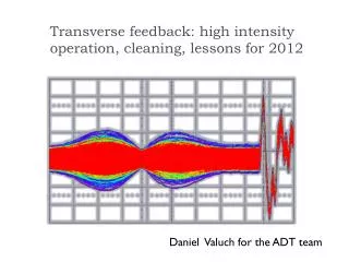
Feedback as cure • coherent signals visible for both ecloud and TMCI instability • provided reaction time (few turns) shorter than growth times • feedback in principle should work sum difference (delta) instability growing (TMCI) signals up to 1.6 GHz turns frequency R. de Maria et al. DIPAC 2009, MOPD17 W. Hofle / LIU review 17.11.2011
e-cloud vertical instability sum difference (delta) quadrupolar motion (longitudinal) at injection due to voltage mismatch artifact from pick-up (beam pipe cut-off) instability growing signals up to 1.2 GHz turns frequency R. de Maria et al. DIPAC 2009, MOPD17 W. Hofle / LIU review 17.11.2011
e-cloud vertical instability R. de Maria et al. DIPAC 2009, MOPD17 W. Hofle / LIU review 17.11.2011
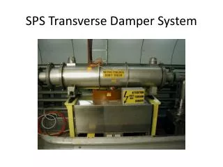
existing hardware simulated, no cables pick-up, also used as kicker since this year looking in beam direction “forward” backward (BPW 319.01) now kicker forward (BPW 321.01) simulated, with cable measured response ultra-short bunch W. Hofle / LIU review 17.11.2011
Feasibility of feedback in simulations • simulations have focused up to now on ecloud instability • initial study done in 2008 with headtail (J. Thompson et al.) • this study showed feasibility in principle, but simple FB model • focused on 55 GeV (SPS injection with PS2) • repeated since using WARP code (J. L. Vay, R. Secondo et al.) • future: CMAD (C. Rivetta et al.) ? • TMCI best accessibly through headtail • due to good modeling of SPS Impedance in this code • re-launch simulations with headtail • also look at interplay of impedance and e-cloud J. Thompson et al. CERN-AB-2008-070 PAC 2009 FR5RFP076 W. Hofle / LIU review 17.11.2011
Recent results (WARP code) –(1) suppression of emittance growth demonstrated high feedback gain required no feedback growth Suppressed for G=0.2 emittance increase J. L. Vay R. Secondo (LBNL) PAC 2011 W. Hofle / LIU review 17.11.2011
Recent results (WARP code) – (2) suppression of emittance growth demonstrated high feedback gain required head kicks tail time (turns) J. L. Vay R. Secondo (LBNL) PAC 2011 W. Hofle / LIU review 17.11.2011
Recent results (WARP code) – (3) need to review these parameters and agree on a set for the upgrade; address higher energies in the simulations J. L. Vay R. Secondo (LBNL) PAC 2011 W. Hofle / LIU review 17.11.2011
Limitations of the simulations • action of feedback can only be followed over a very limited • number of turns in the simulations • difficult to quantify the impact of numerical noise on the • estimation of the required kick strength and the emittance • growth; incoherent effects in case of e-cloud hard to • quantify • multi-bunch effects neglected so far • more simulations will give us only an incremental increase in confidence with regards to the feasibility • adopt a staged experimental approach W. Hofle / LIU review 17.11.2011
R&D and staged implementation: The Path (1) Boundary conditions: LS1: 2012 LS2: 2017+ Phase 1:The demonstrator end 2012 minimum goal: damp head tail motion of single bunch existing equipment (amplifiers, BPWs as kicker and PU) electronics (LARP), close FB loop all design specifications for phase 2: end of 2012 Phase 2: New pick-up, new kicker, consolidated electronics, higher power amplifiers, preparation of LSS3 in LS1 for installation of equipment at the end of LS1 or later in a short winter shutdown post-LS1 feedback on multi-bunch beam in presence of e-cloud decide on final implementation and LSS3 vs. LSS5 before LS2 W. Hofle / LIU review 17.11.2011
R&D and staged implementation: The Path (2) Phase 3:Final implementation in LS2 depending on desired energy range upgrade power and if impossible to install in LSS3 for reasons of space or radiation move to LSS5 add kicker modules if required design and construct final electronics (profit from latest technology) commission after LS2 W. Hofle / LIU review 17.11.2011
(a) schedule go/no-go phase 2: go/no-go phase 3: Year 1 Year 2 Year 3 Year 4 Year 5 Year 6 Year 7 2011 2012 2013 2018 2014 2015 2016 2017 Phase 1: demonstrator power amplifiers for phase 2 tendering (s) new pick-up design and construction kickers design and construction Phase 2: phase 2 beam tests Phase 3: implementation
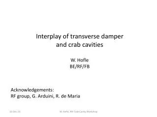
New pick-up • long precision coupler (separate the “reflection”) • reserve 2 m space close to a QD in LSS3 (straight section) • free space during LS1 (reshuffle some equipment, • under discussion with Eric) • install cabling in LS1 and dummy chamber if PU not ready • for highest frequency reach go for smallest diameter • circular vacuum chamber • (define with ABP when location decided) • E. Montesinos interested in design and fabrication, • lead time (!) W. Hofle / LIU review 17.11.2011
E. Montesinos PU kicker
New kickers • short striplines, or split band approach ? • location: dispersion suppressor, flat chamber • frequency reach < 1.5 GHz • cabling in LS1, preparation of space W. Hofle / LIU review 17.11.2011
Questions ? W. Hofle / LIU review 17.11.2011