Download
1 / 18
180 likes | 303 Views
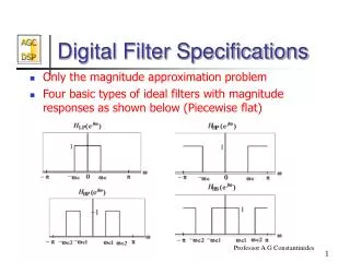
The New GHz Pulsar Digital Filter Bank System. Grant Hampson ATNF Research Engineer 23 November 2005. Pulsar Digital Filter Bank (PDFB) User Requirements. There are too many user requirements for the Pulsar DFB to listed here, but in short, the following are minimum requirements:

E N D
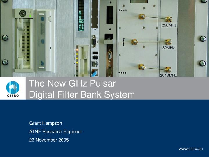
The New GHz Pulsar Digital Filter Bank System Grant Hampson ATNF Research Engineer 23 November 2005
Pulsar Digital Filter Bank (PDFB) User Requirements • There are too many user requirements for the Pulsar DFB to listed here, but in short, the following are minimum requirements: • ADC: 8-bit sampling • 1GHz of output bandwidth • Dual polarisation • 2048 frequency channels • 2048 pulsar phase bins • 4-product correlator • 4ms minimum pulsar period(for this product-channel-bin combination) • There are many other modes to the PDFB system including a Raw DataCapture, Spectrometer, and PulsarSearch mode. 4ms
PDFB System Design • The PDFB system is designed around a Compact PCI 6U chassis. • Dual ADC designed by Paul Roberts for CABB developments • Pulsar Timing Unit designed by Evan Davis for WBC • cPCI, DFB, PPU and Synthesizers designed by Grant and Andrew • All components contained in a single 7U-19”rack unit 465mm deep Gain Mode Pol.A Dual ADC 8-bit 2GSPS Digital Filter Bank Four Product Correlator Raw Data Capture Spectrometer Pulsar Search Pulsar Folded QDR Memory Compact PCI System Power, Drives IO, etc. Pol.B 5MHz Synthesizers Pulsar Timing Unit 1pps
PDFB System (Front View) PTU Display Event Generator DFB Display IDE HD DVD/CD CPU 2GHz & 256MHz Keyboard, mouse, monitorcan be connected at front(or rear)if desired ATDC,two IF’s, network connectat front 7U 1U Fan Tray SCSI HD 3.5” FLOPPY DV4 & ADC 32MHz
PDFB System (Rear View) Pulsar Timing Unit Calibration Output 5MHz & 1pps station reference signals Voltage Current Meters PC supply(as well as Drives and PTU) ADC & DFB supply Only AC power, 5MHz, 1pps, Calibrator, connected to rear
Compact PCI • The PDFB system is designed around a Compact PCI 6U card size. • The CPU board is a 1.5GHz M-processorwith 2GB of memory from Advantech • The cPCI form factor is 233x160mm which is sufficient space for a DFB PCB card • Lots of peripherals available in cPCI format- we use an RTM for a SCSI320 driver, etc. • Rack hardware for 7U cPCI available from Rittal.(The power supplies, fans, rack, etc. all from Rittal) • If desired the cPCI card can be placed inside a PC using an adapter card(however the user still requires the synthesizers, etc. to operate)
There six options for data storage on the PDFB system: The PC system drive (a 2.5" 40Gbyte) harddrive will containall the OS and PDFB/correlator software (no data storage!) Dual SCSI hard drives, each with a capacity of 300Gbytes,total 600Gbytes (direct storage for all outputs of the system) Single IDE hard drive with a capacity of also 300Gbytes(secondary storage, temporary data, etc.) A DVD/CD burner is also in the systemif you need a smaller amount of storage (1-5Gbytes.) There are USB2.0 ports on the front of the PC to attach USB drives if you wish to. The PC also has Gigabit ethernet if you would liketo quickly offload the data to another system PDFB Data Storage 3.5” FLOPPY DVD/CD IDE HD SCSI HD USB ports Network
Frequency Synthesizers There are three frequency synthesizers in the PDFB system: • Pulsar Timing Unit – contains a 128MHz clock for timing of PTU signals(this is referenced to 5MHz and synchronized with the 1pps signal.) • ADC/DFB Reference – contains a synthesizer to generate 32MHz from the 5MHz reference and synchronized with the 1pps signal. • ADC/DFB – contains two synthesizers which use the 32MHz reference to generate the ADC sampling clock of 2.048GHz, and the processing clock of the DFB, equal to 256MHz. 5MHz PTU Signals (Bank, Period, Bin, calibrator, etc.) 1pps 2.048GHz Dual Synthesizer 256MHz 32MHz Synthesizer
Dual 8-bit 2GSPS Digitisers The Pulsar DFB system will use the sampler used in the CABB updgrade: • Two Atmel 10-bit 2GSPS ADC are used – one for each polarisation.(In CABB the two ADC streams are combinedto make a 4GSPS ADC.) • Each ADC samples at 2.048GHz, and most likely only 8-bits of data will be transmitted due to the high volume of data. (The ADC only has 7 effective number of bitsat this sample rate.)
Pulsar DFB Processing Engine The signal processing engine of the Pulsar DFB system is the Dual V4 Board: • 2 - Xilinx Virtex-4 FPGAs • 12 - Samsung QDR memories • cPCI interface 32-bit/33MHz • FPGAs/QDR processesdata at 256MHz • Multi-Gigabit tranceivers- data in/out/between FPGAs • … • Refer to Andrew Browns presentation on the DV4 for more information
The key to success in the pulsar processing unit is the memory BW requiredto achievethefolded data mode processing requirements (not quantity) The memory bandwidth required can be calculated using:Processing rate x integration size x parallel data paths x simultaneous R/W 256MHz x 24-bit x 16 x 2 = 24Gbytes/second! (192Gbits/second!!) There are many types of memory on the market – but none quite have the memory BW advantage of QDR-II memory QDR architecture has independent read and write data paths Both paths use Double Data Rate (DDR) transmission The integration size was chosen to be 24-bits as this was a physical limitation set by the number of IO pins available on the FPGA Six QDR chips are required on each FPGA, total 48+48=96Mbytes(there are two FPGAs to enable double buffering) Why QDR Memory?
Matlab, Simulink and Xilinx System Generator • Matlab is a powerful text based simulation tool • Simulink is a powerful graphical based simulation tool • The combination makes it the ultimate simulation tool(Matlab generates stimulus Simulink Matlab analyzes results) • Xilinx System Generator converts the Simulink Models to VHDL code • VHDL wrappers connect the VHDL model to the physical IO interfaces(e.g. DDR, clocks, DCMs, constraints, etc.) • The VHDL is compiled using Xilinx ISE7.1 to produce FPGA bitfiles VHDL Wrapper MatlabStimulus & Analysis SimulinkModels Xilinx SystemGenerator VHDL SimulinkModel Xilinx VHDL Synthesis Bitfile Programs FPGAs
Digital Filter Bank Configurations • The Digital Filter Bank (DFB) input is real ADC samples • The DFB processes them into a number of frequency channels using a polyphase filtering method. • There are two distinct parts to the DFB;a filtering stage (FIR) followed by a frequency transform (FFT) • Depending on the bandwidth of the input data– it becomes feasible to separate the data over several data paths– which gives rise to the radix of the design. • In order to process 1GHz of BW (2GSPS real) this is dividedover 8 data buses (a Radix-8 design) each operating at 256MHz. • Fully custom Radix-2, Radix-4, Radix-8 DFB’s have been developed for BW’s of 256, 512, 1024MHz. • As the BW reduces the Radix of the design decreases and at BW’s below 256MHz it is possible to use the Xilinx FFT Pol.A ADC’s FIRPart FFT Part PPU Part Radix-R Radix-R Radix-R Pol.B
Pulsar Processing Unit (PPU) Modes There are four fundamental modes in the PPU: • Raw Data Capture of ADC samples and DFB output (parameters: BW, number of samples) • Spectrometer (parameters: BW, products, channels, bits) • Pulsar Search Mode (parameters: BW, products, channels, bits, integration time) • Pulsar Folded Mode (parameters: BW, products, channels, bins, bits) Each of these modes is customizable to suit the user application. The PPU processes many parallel data streams simultaneously (Radix-R)
Pulsar Search Mode Search controlledby number of untegrationsper output Can control output rate by truncatingoutput bits, and/or number of products 39-80MB/s sustained Gain DFB/Correlator PPU Search Mode QDR Memory Read Results PCI Bus SCSI Hard Drive 32-bit/33MHz50% efficient66MBytes/secTime to download:Radix-2:182msRadix-4: 364msRadix-8: 727ms Time to Fill Memory = 2M deep / (256MHz/Integrations) = integrations / 128 Radix-2:12MbytesRadix-4:24MbytesRadix-8:48Mbytes Minimum Integration SettingRadix-2: 24Radix-4: 47Radix-8: 93 * note that this is for 4-products no truncation setting determinesthe “sampling rate” andrange of pulsar frequencythat can be “searched”
DFB channels PSR Bins 64 128 256 512 1k 2k 4k 8k 64 128 ¼ 256 ¼ ½ 512 ¼ ½ 1 1k ¼ ½ 1 2 2k ¼ ½ 1 2 4 4k ¼ ½ 1 2 4 8k ½ 1 2 4 Pulsar Folded Mode • The Pulsar Folded Mode is the main mode of the PDFB • The PTU generates timing signals at the pulsar frequency (or period) • Each pulsar period can be divided into many phase-bins • Depending on the BW of the input data and the number of DFB frequency channels the data can be folded at a particular rate (see table below) • By modifying the BW and/or frequency-channels and/or phase-binsit is possible to change the folding rate. Approximate Minimum Pulsar Period (in ms)for a 1024MHz BW, 4-product PSRDFB(yellow is proposed, gray not possible with this BW)
Conclusions • The Pulsar Digital Filter Bank System is a fully integrated solutioncontained in a small 7U rack. • As much flexibility as possible has been designed into the system. • The heart of the PDFB is two programmable FPGAsthat can deliver a multitude of processing configurations • All hardware exists in system – awaiting testing(although the FPGAs are still engineering samples) • Basic firmware exists for the various components • Still lots of work to do … firmware, software, testing, integration, etc., etc.
Thank You Contact CSIRO Phone 1300 363 400 +61 3 9545 2176 Email enquiries@csiro.au Web www.csiro.au ATNF / Electronics Group Name Grant Hampson Title Research Engineer Phone (eg. +61 3 9372 4647) Email grant.hampson@csiro.au Web www.atnf.csiro.au