Download
1 / 20
260 likes | 504 Views
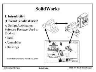
SolidWorks Teacher Guide Lesson11. School’s Name Teacher’s Name Date. What is PhotoWorks?. A software application that creates realistic images from SolidWorks models. PhotoWorks uses rendering effects such as: Materials Lights Shadows Backgrounds. Shaded Rendering.

E N D
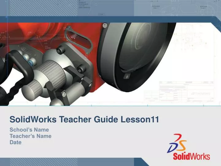
SolidWorks Teacher Guide Lesson11 School’s Name Teacher’s Name Date
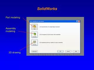
What is PhotoWorks? A software application that creates realistic images from SolidWorks models. PhotoWorks uses rendering effects such as: • Materials • Lights • Shadows • Backgrounds
Shaded Rendering • The basis for images in PhotoWorks. • Shaded Rendering requires a material. • The default material is Plastic. To display the Shaded Rendering: • Click Render on the PhotoWorks toolbar.
Materials Materials specify the properties of a model’s surface. Properties are: • Color • Texture • Surface Finish • Illumination
To Apply the Chromium Plate Material: • Click Material on the PhotoWorks toolbar. • Expand the metals folder. • Open the sub-folder chrome. • Select chromium plate. • Click Apply, Close. • Click Render .
Image Background The portion of the graphics area not covered by the model. • Background styles vary in complexity and rendering speed. • Background styles controlled by Scene Editor. • Incorporate advanced rendering effects into a PhotoWorks Scene. • Shadows • Reflections
To Change the Background Style to Clouds: • Click Scene on the PhotoWorks toolbar. • Expand the Backgrounds folder. • Open the sub-folder scaled_image. • Select image clouds. • Click Apply.
To Save the Image File • Click Render to File on the PhotoWorks toolbar. • Enter a file name. • Specify a file type. • Click Render.
SolidWorks Animator Application What is SolidWorks Animator? • SolidWorks Animator animates and captures motion of SolidWorks parts and assemblies. • SolidWorks Animator generates Windows-based animations (*.avi files). The *.avi file uses a Windows-based Media Player. • SolidWorks Animator can be combined with PhotoWorks.
Renderer Options The Renderer affects the quality of the saved image. There are two options: • SolidWorks screen • PhotoWorks buffer
Factors Affecting File Size • Number of frames per second • Renderer used • PhotoWorks buffer creates a larger file than SolidWorks screen • If using PhotoWorks buffer: • Materials • Background • Shadows • Multiple-light sources • Video compression • Key frames
To Create an Exploded View: • Click Open on the Standard toolbar, and open the assembly, Tutor. • Click Exploded View on the Assembly toolbar.The Assembly Explode dialog appears.
Creating an Exploded View: • Click on the component to explode to begin a new explode step. Drag the component to the explode location.The dialog box contains selection lists for: • Component(s) to explode • Direction to explode along • Distance
Creating an Exploded View: • Click the component to explode, in this case Tutor1. The component name appears in the dialog.Select the desired explode direction from the model triad. This selection is indicated in the Direction area of the dialog (Along Z, Z@Tutor.SLDASM by default).
Creating an Exploded View: • Drag the component to the desired distance. Release the mouse button to create the Explode step. • Edit the step (right-click on the new Explode step, and select Edit Step) to adjust the Distance to exactly 70mm and click Apply in the dialog. • Since there is only one component to explode, this completes making the exploded view. Click OK to close the Assembly Explode dialog box.
Creating an Exploded View: • Results.Note: Exploded views are related to and stored in configurations. You can only have one exploded view per configuration.
Collapsing an Exploded View: • Right-click the assembly icon in the FeatureManager design tree, and select Collapse from the shortcut menu. To Explode an Existing Exploded View: • Right-click the assembly icon in the FeatureManager design tree, and select Explode from the shortcut menu.