Download

1 / 24
260 likes | 642 Views
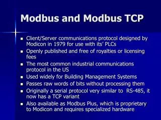
TOP Server: Understanding Modbus for Device Connectivity. Presenter: Kevin Rutherford. Modbus Protocol Training Agenda. Overview Modbus Protocol Specifics Modbus Types Modbus Terminology Modbus “Quirks” Example Modbus packets TOP Server Modbus Suite Flexibility Supported Protocols

E N D
TOP Server: Understanding Modbus for Device Connectivity Presenter: Kevin Rutherford
Modbus Protocol TrainingAgenda • Overview • Modbus Protocol Specifics • Modbus Types • Modbus Terminology • Modbus “Quirks” • Example Modbus packets • TOP Server Modbus Suite Flexibility • Supported Protocols • Dealing with “Non-Standard” Modbus Devices • Live Modbus Demo • Configuration • Troubleshooting • Using Quick Client • Using Channel Diagnostics • Questions?
What is a Protocol? • Protocols can happen at many levels and cover many things • Cabling • Electrical • Packet structure • Content of Packets • Timing of Packets • Rarely does ONE protocol cover all of these things • Multiple protocols involved in making a full connection
Application Protocols – Modbus TCP = Contents of the Train Cars Network Protocol Transport – TCP/IP Ethernet, FTP, HTTP = The train and cars Physical Transport Media- RS-232, RS-422, 10-Base-T = The Train Tracks What is a Protocol? Analogy – Train Tracks, Cars, & Cargo • RS-232, 485, Ethernet define cabling and electrical protocols, i.e. the Train Tracks… • In Ethernet connections, the transport defines the Train Cars (Packet structure) • In Serial connections, the application protocol usually defines the Train Cars • What’s in the Train Cars (packets) is the Cargo – the data – which is defined by the actual device/application protocol….
Parts of a Typical Application Protocol • Many application protocols use some or all of these in their structures: • Header/start characters • Target Device ID • Function Code, Sub-Function Codes • Data Length • Data • Checksum/error checking • Termination character • Data section usually contains • Read: Memory type, start location, length, or multiple locations in some protocols • Write: Memory type & location to write, size to write, actual data to write • Data contents is usually driven by what Function Code or Sub-Function Codes are used in the request • Data is OFTEN communicated in Hex – Base 16!!!!
Modbus – Used Everywhere! • Schneider/Modicon/Telemecanique PLCs • Nearly every other PLC brand offers built-in Modbus or a Modbus option module • Electrical transmission & distribution control & monitoring equipment • Water/wastewater control equipment • Temperature controllers • AC Variable Speed Drives • Servo Drives • Pick a device – it just might support Modbus • When in doubt – find out – is Modbus a choice on the hardware?
Modbus Types • Serial – RS-232/422/485 electrical protocol • Two possible transmission modes: • Modbus RTU • Modbus ASCII • Proprietary – Vendor specific electrical protocol • Modbus Plus • Ethernet – standard TCP/IP Ethernet electrical +transport • Modbus TCP or Modbus Ethernet • Ethernet Encapsulated Modbus RTU or ASCII • Gateway Devices • Ethernet or Modbus Plus • Modbus RTU or ASCII serial on other side • Multiple serial devices on downstream side
Modbus Terminology • Memory Types & Addressing • Input coils = Digital inputs • 1xxxxx address type • 0/1 values • Boolean data type • Output Coils = Digital outputs • 0xxxxx address type • 0/1 values • Boolean data type • Input Registers = Analog inputs • 3xxxxx address type • 16-bit registers • 32-bit data types use two consecutive registers • Holding (Output) Registers = Analog outputs • 4xxxxx address type • 16-bit registers • 32-bit data types use two consecutive registers
Modbus Terminology • Read/Write Access • Read Only: Input registers & Input Coils • Read/Write: Output Coils and Holding Registers • Addressing – 5 or 6 digits • Original Modbus was 5 digits – i.e. 40001 • As PLC memories grew, went to 6, i.e. 400001 • Offset • Modbus address offset is all digits after the first digit identify which memory type the address is • Can be 0 or 1 based • Pointer that specifies where into that memory type to go and start getting data or writing data
Modbus Terminology • Modbus Node Address • Used with serial devices • Each device on serial connection has unique ID • Slave ID values = 1 to 247 • Master’s don’t have a Node address • Modbus Function Codes • Used by Modbus Masters to tell a Modbus Slave what they want it to do • Read or Write? • Memory Type? • Single item or Multiple Items in a Transaction
Modbus Terminology • Common Modbus Function Codes • 01 – Read Coils (output coils), 0xxxxx memory • 02 – Read Discrete Inputs (input coils), 1xxxxx memory • 03 – Read Holding Registers, 4xxxxx memory • 04 – Read Input Registers, 3xxxxx memory • 05 – Write Single coil (outputs), 0xxxxx memory • 06 – Write single Holding Register, 4xxxxx memory • 15 (0x0F) – Write multiple coils (outputs) • 16 (0x10) – Write multiple Holding Registers
Modbus Terminology • Modbus Exception Codes • Used by slaves to tell Master what it did not like about a request • Examples: • 02 - Bad memory address • 01 - I don’t understand this function code • 0x0B - Slave didn’t respond – gateway devices
Common Modbus Quirks • Data Byte Ordering • 32 bit data type word order • 64 bit data type Dword order • Byte order within words • Addressing – 0 or 1 based • Function Code support • Use of user definable function codes • Non-Modicon use of memory type + offset for addressing in documentation confusing
Modbus RTU Packet Framing • PDU = protocol data unit • Address field – 1 byte – node address of the slave • CRC = error checking calculation, 2 bytes • Function Code + Data depends on what you want to accomplish.
Modbus Packet FormatModbus RTU • A MODBUS message is placed by Modbus Master into a serial frame that has a known beginning and ending point. • This is an amount of time indicating to devices that receive a new frame to begin at the start of the message, and to know when the message is completed. • In RTU mode, message frames are separated by a silent interval of at least 3.5 character times. Character time= time to send one byte @ chosen baud rate
Modbus RTU ExampleRead Holding Registers 108-110 from Slave Node 01 • Transmit: TX: 01 03 00 6B 00 03 xx xx • Receive: RX: 01 03 06 02 2B 00 00 00 64 xx xx xx xx = 2 byte checksum IMPORTANT Notice: • Request is in # of registers • Response is in # of bytes • 1 Register = 2 bytes
Modbus RTU ExampleWrite Single Holding Register 2 with value of 3 on Slave Node 1 xx xx = 2 byte checksum • Transmit: TX: 01 06 00 01 00 03 xx xx • Receive: RX: 01 06 00 01 00 03 xx xx
Modbus RTU ExampleException Response • Master asks for memory address that doesn’t exist in the slave
Modbus Packet FormatModbus TCP • A Modbus TCP Packet is put into a TCP/IP wrapper • Notice similarity to Modbus RTU with function code + data • MBAP Header=Modbus Application Protocol Header – similar to the address field in the serial framing • MBAP = 7 extra bytes on beginning of transmission
Modbus TCP MBAP HeaderContents • Unit identifier used when using bridging to downstream serial devices. 0 = no bridging being used
Modbus TCP - Example • Reading Input Register 30070, Reading through a gateway to slave device ID 1 on serial connection • Request: • TX: 08 3B 00 00 00 06 01 04 00 46 00 01 • 08 3B 00 00 00 06 01 = MBAP • 08 3B = Transaction ID • 00 00 = Protocol ID • 00 06 = 6 bytes follow from here • 01 = Node ID 1 • 04 00 46 00 01 = regular Modbus Read input Registers command • 04 = Function Code • 00 46 = Starting address in hex 0x46 = 70 decimal = offset into input registers • 00 01 = Quantity of input registers to read • Response • RX: 08 3B 00 00 00 05 01 04 02 01 23 • 08 3B 00 00 00 05 01 = MBAP • 08 3B = Transaction ID – notice this matches the request • 00 00 = Protocol ID • 00 05 = 5 bytes follow from here • 01 = slave ID 1 • 04 02 01 23 = regular response to Modbus Read Input Registers • 04 = Function Code • 02 = byte count • 01 23 = Value in hex = 291 Decimal
TOP Server Modbus Suite Flexibility • Protocols Supported • Modbus RTU Serial Master and Slave • Modbus ASCII Master • Modbus Plus • Modbus TCP Ethernet Master and Slave • Flexible Settings for Non-Standard Modbus • Zero or One-Based Addressing • Holding Register Bit Mask Writes • Specifying Function Code for Writes • Data order manipulation
Live Demo • Overview • Modbus Protocol Specifics • Modbus Types • Modbus Terminology • Modbus “Quirks” • Example Modbus packets • TOP Server Modbus Suite Flexibility • Supported Protocols • Dealing with “Non-Standard” Modbus Devices • Live Modbus Demo • Configuration • Troubleshooting • Using Quick Client • Using Channel Diagnostics • Questions?
Questions? • Questions later? • Kevin Rutherford • krutherford@softwaretoolbox.com • 704-849-2773 x1326 • support@softwaretoolbox.com • TOP Server Modbus Suite (Info / Free Demo) • http://www.toolboxopc.com/html/modbussuite.html • Other learning opportunities • Visit www.softwaretoolbox.com/webinars