Download
1 / 29
290 likes | 307 Views
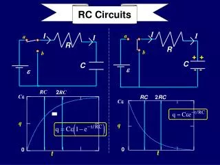
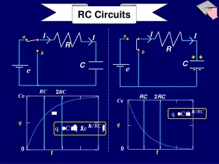
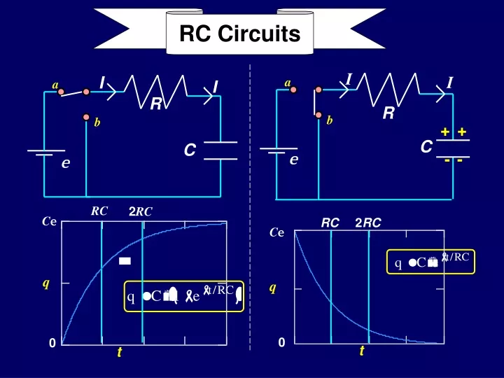
I. I. I. a. I. a. R. R. b. b. +. +. C. C. e. -. -. e. RC Circuits. RC. 2 RC. C e. RC. 2 RC. C e. q. q. 0. 0. t. t. Today…. Calculate Discharging of Capacitor through a Resistor Calculate Charging of Capacitor through a Resistor. Review: Behavior of Capacitors.

E N D
I I I a I a R R b b + + C C e - - e RC Circuits RC 2RC Ce RC 2RC Ce q q 0 0 t t
Today… • Calculate Discharging of Capacitor through a Resistor • Calculate Charging of Capacitor through a Resistor
Review: Behavior of Capacitors • Capacitors resist change in charge and voltage • Charging • Initially, the capacitor behaves like a wire. • After a long time, the capacitor behaves like an open switch. • Discharging • Initially, the capacitor behaves like a battery. • After a long time, the capacitor behaves like a wire.
Preflight 11: E The capacitor is initially uncharged, and the two switches are open. 3) What is the voltage across the capacitor immediately after switch S1 is closed? Initially:Q = 0 VC = 0 I = E/(2R) a) Vc = 0 b) Vc = E c) Vc = 1/2 E 4) Find the voltage across the capacitor after the switch has been closed for a very long time. Q = E C I = 0 a) Vc = 0 b) Vc = E c) Vc = 1/2 E
Preflight 11: E 6) After being closed a long time, switch 1 is opened and switch 2 is closed. What is the current through the right resistor immediately after the switch 2 is closed? a) IR= 0 b) IR=E/(3R) c) IR=E/(2R) d) IR=E/R Now, the battery and the resistor 2R are disconnected from the circuit, so we have a different circuit. Since C is fully charged,VC = E. Initially, C acts like a battery, andI = VC/R.
I I a R b + + C e - - RC Circuits (Time-varying currents -- discharging) • Discharge capacitor: • C initially charged with Q = Q0 = Ce • Connect switch to batt = 0. • Calculate current and charge as function of time. • Loop theorem • Convert to differential equation forQ: Note: Although we know the current is flowing off the cap., we define it as shown so that …
Note that this “guess” incorporates the boundary conditions: Þ ! dQ Q - - t / RC t / RC e e + = - e + e = R 0 dt C Discharging Capacitor I I a R b + + C e - - • Guess solution: • Check that it is a solution:
Discharging Capacitor I I R b + + C e - - • Current is found from differentiation: Þ • Conclusion: • Capacitor discharges exponentially with time constant t = RC • Current decays from initial max value(= -e/R)with same time constant Minus sign: Current is opposite to original definition, i.e., charges flow away from capacitor. • Discharge capacitor: a
zero 0 Current “Max”= -e/R 37%Max att = RC I -e /R Discharging Capacitor RC 2RC Ce Charge on C Max = Ce 37% Max at t = RC Q 0 t t
Preflight 11: Initially, the charges on the two capacitors are the same. But the two circuits have different time constants: t1 = RC and t2 = 2RC.Sincet2 > t1it takes circuit 2 longer to discharge its capacitor. Therefore, at any given time, the charge on capacitor 2 is bigger than that on capacitor 1. The two circuits shown below contain identical fully charged capacitors att=0. Circuit 2 has twice as much resistance as circuit 1. 8) Compare the charge on the two capacitors a short time after t = 0 a) Q1 > Q2 b) Q1 = Q2 c) Q1 < Q2
a b R 3R C (c) t0 > t (b) t0 = t (a) t0 < t (c) (b) (a) 1A 1B Lecture 11, ACT 1 • The capacitor in the circuit shown is initially charged to Q = Q0. At t = 0 the switch is connected to positiona. • At t = t0 the switch is immediately flipped from position a to positionb. • Which of the following graphs best represents the time dependence of the charge on C? • Which of the following correctly relates the value of t0 to the time constant t while the switch is at a?
a b R 3R C (c) (b) (a) 1A Lecture 11, ACT 1 • The capacitor in the circuit shown is initially charged to Q = Q0. At t = 0 the switch is connected to positiona. • At t = t0 the switch is immediately flipped from position a to positionb. • Which of the following graphs best represents the time dependence of the charge on C? • For 0 < t < t0, the capacitor is discharging with time constantt = RC • For t > t0, the capacitor is discharging with time constant t= 3RC, i.e., much more slowly. Therefore, the answer is (a) • (b) has equal discharging rates • (c) has fasterdischarging after t0than before.
a b R 3R C (c) t0 > t (b) t0 = t (a) t0 < t 1B • Which of the following correctly relates the value of t0 to the time constant t while the switch is at a? Lecture 11, ACT 1 • The capacitor in the circuit shown is initially charged to Q = Q0. At t = 0 the switch is connected to positiona. • At t = t0 the switch is immediately flipped from position a to positionb. We know that for t = t, the value of the charge is e-1 = 0.37 of the value at t = 0. Since the curve shows Q(t0) ~ 0.6 Q0, t0must be less than t.
I I a R b C e Would it matter where R is placed in the loop?? RC Circuits(Time-varying currents, charging) • Charge capacitor: • Cinitially uncharged; connect switch toaat t=0 Calculate current and charge as function of time. • • Loop theorem Þ • Convert to differential equation for Q: No!
I I a R b C e Note that this “guess” incorporates the boundary conditions: ! Charging Capacitor • Charge capacitor: • • Guess solution: • Check that it is a solution:
I • Charge capacitor: I a R b C e Þ • Conclusion: • Capacitor reaches its final charge(Q=Ce ) exponentially with time constant t = RC. • Current decays from max (=e /R) with same time constant. Charging Capacitor • Current is found from differentiation:
Charge on C Max = Ce 63% Max at t = RC Current Max =e /R 37% Max at t = RC Charging Capacitor RC 2RC Ce Q 0 t e /R I 0 t
(c) Q2 > 2Q1 (b) Q2 = 2Q1 (a) Q2 < 2Q1 Lecture 11, ACT 2 a I I • At t=0 the switch is thrown from positionb to position ain the circuit shown: The capacitor is initially uncharged. • At time t = t1 =t, the charge Q1 on the capacitor is (1-1/e) of its asymptotic charge Qf = Ce. • What is the relation between Q1 and Q2 , the charge on the capacitor at timet = t2 = 2t ? R b e C R
(c) Q2 > 2Q1 (b) Q2 = 2Q1 (a) Q2 < 2Q1 • The point of this ACT is to test your understanding of the exact time dependence of the charging of the capacitor. • Charge increases according to: • So the question is: how does this charge increase differ from a linear increase? 2Q1 Q2 • From the graph at the right, it is clear that the charge increase is not as fast as linear. • In fact the rate of increase is just proportional to the current(dQ/dt)which decreases with time. • Therefore, Q2 < 2Q1. Q1 Q t 2t Lecture 11, ACT 2 a I I • At t=0 the switch is thrown from positionb to position ain the circuit shown: The capacitor is initially uncharged. • At time t = t1 =t, the charge Q1 on the capacitor is (1-1/e) of its asymptotic charge Qf = Ce. • What is the relation between Q1 and Q2 , the charge on the capacitor at timet = t2 = 2t ? R b e C R
0 I -e /R Charging Discharging RC RC 2RC 2RC Ce Ce Q Q 0 0 t t e /R I 0 t t
I1 I2 I3 e C R2 R1 A very interesting RC circuit First consider the short and long term behavior of this circuit. • Short term behavior: • Initially the capacitor acts like an ideal wire. Hence, • and • Long term behavior: • Exercise for the student!!
Preflight 11: After the switch is closed for a long time ….. The capacitor will be fully charged, andI3 = 0.(The capacitor acts like an open switch). So,I1 = I2,and we have a one-loop circuit with two resistors in series, henceI1 = E/(R1+R2) The circuit below contains a battery, a switch, a capacitor and two resistors 10) Find the current through R1 after the switch has been closed for a long time. a) I1 = 0 b) I1 = E/R1 c) I1 = E/(R1+ R2)
I1 I2 I3 e C R2 R1 3B 3A Lecture 11, ACT 3 • At t = 0 the switch is closed in the circuit shown. The initially uncharged capacitor then begins to charge. • What will be the voltage across the capacitor a long time after the switch is closed? (c) VC = e (b) VC = e R2/(R1+ R2) (a) VC = 0 • What is the charging time constant t? (c) (b) (a)
I1 I2 I3 e C R2 R1 3A After a long time the capacitor is completely charged, so no current flows through it. The circuit is then equivalent to a battery with two resistors in series. The voltage across the capacitor equals the voltage across R2 (since C and R2 are in parallel). Either from direct calculation, or remembering the “Voltage Divider Circuit”, VC = VR2 = e R2/(R1+ R2). Lecture 11, ACT 3 • At t = 0 the switch is closed in the circuit shown. The initially uncharged capacitor then begins to charge. • What will be the voltage across the capacitor a long time after the switch is closed? (c) VC = e (b) VC = e R2/(R1+ R2) (a) VC = 0
I1 I2 I3 e C R2 R1 3B Lecture 11, ACT 3 • At t = 0 the switch is closed in the circuit shown. The initially uncharged capacitor then begins to charge. • What is the charging time • constant t? (c) (b) (a) • An ideal voltage source contributes no resistance or capacitance • time constant is entirely determined by C, R1, and R2. • I personally find it easier to think about the circuit as if C was discharging than charging; I imagine that the capacitor is charged, and that the battery is replaced by a wire (which also has no resistance or capacitance). Since the battery supplies a constant voltage, it doesn’t affect the time constant. • We simply need to find the effective resistance Reff through which the capacitor (dis)charges. Looking at the new circuit, it is clear that the capacitor would be (dis)charging through bothR1 and R2, which are in parallel their effective resistance is Reff = R1R2/(R1 + R2)and t = ReffC.
Loop 2 • Loop 1: I1 I2 I3 Loop 1 e C • Loop 2: R2 • Node: R1 • EliminateI1 inL1 and L2 using Node equation: eliminate I2 from this • Loop 1: • Loop 2: • Final differential eqn: Very interesting RC circuit , detailed
Loop 2 • Final differential eqn: I1 I2 I3 Loop 1 e C R2 R1 time constant: t parallel combination of R1 and R2 Very interesting RC circuitcontinued • Try solution of the form: • and plug into ODE to get parameters A and τ • Obtain results that agree with initial and final conditions:
Loop 2 I1 I2 I3 Loop 1 e C R2 R1 I2 e C R2 R1 Different time constant for discharging Very interesting RC circuitcontinued • What happens when we • discharge the capacitor? • Open the switch... • Loop 1 and Loop 2 do not exist! • I2is only current • only one loop • start atxmarks the spot...
Summary • Kirchoff’s Laws apply to time dependent circuitsthey give differential equations! • Exponential solutions • from form of differential equation • time constantt = RC • whatR, whatC??You must analyze the problem! • seriesRC charging solution • seriesRCdischarging solution Next time: Start Magnetism