Download
1 / 63
630 likes | 752 Views
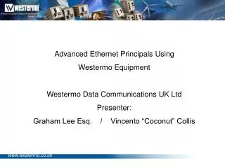
Advanced Ethernet Principals Using Westermo Equipment Westermo Data Communications UK Ltd Presenter: Graham Lee Esq. / Vincento “Coconut” Collis. Schedule for the day: Blahblahblah Blahblahblah Followed by: Cake. The WeOS (Westermo Operating System) concept.

E N D
Advanced Ethernet Principals Using Westermo Equipment Westermo Data Communications UK Ltd Presenter: Graham Lee Esq. / Vincento “Coconut” Collis
Schedule for the day: Blahblahblah Blahblahblah Followed by: Cake
The WeOS (Westermo Operating System) concept • WeOS was created in response to market demand • Westermo listened to customer demand’s for L2 Switching and L3 Routing • The management setup had to be easy to use by ICA and PLC engineers • Support for a CLI (Command Line Interface) • The new device had to support; • VLAN’s • Very Fast L2 ring redundancy • Legacy Serial protocol support • VPN’s • Dynamic Routing • Compatible with feature’s found in Enterprise IT equipment • Firewall • But the implementation had to be industrialised, Robust and future Proof!
Interoperability MadeEasy Future Proofed Robust
Interoperability Future Products Exsisting Lynx
WeOS based devices • Family of Layer 3 Switches • High-Performance Ethernet Switch supports: • IGMP • VLAN • FRNT • QoS • Advanced Layer 3 Functions: • Routing • NAT & PAT • OSPF • Firewall • IPsec • Configurable Via: • HTTP, SSH, Telnet, Serial port www.westermo.co.uk
Slot-based construction and port numbering Management port Mix of Ethernet and Fibre ports I/O and fault contact Configurable status LED’s I/O & Fault Contact Status LED’s Management port Slot 1 Management Slots 2 & 3 Additional ports
Red Fox Industrial Configurable in three different ways: Web-screen configuration CLI configuration via SSH and Telnet Serial configuration via console port
A Quick Recap…. The OSI (Open Standards Interconnect) model is a definition of how devices should communicate, each layer performs a defined task and is separate to the layers above and below. Data from higher levels is encapsulated by the lower layers Communication protocols, TCP, UDP IP Addresses, Routers Ethernet, Mac addresses, Switches, Bridges Cat5e Cable, Fibre Optic, DSL, Radio
Preamble Destination MAC Address Source MAC Address Type Field Version IHL Type Of Service Total Length Identification Flags Fragment Offset TTL Protocol Header Checksum Source IP Address Destination IP Address IP Options Padding Src port Seq number Ack Number Data Offset Reserved Dst Port Flags Window Checksum Urgent Pointer Options Cyclic Redundancy Check An Ethernet packet An example packet PDU OSI Layer TCP IP Ethernet Data from upper layers Maximum frame size = 1542 bytes
IP Addresses • 32 Bit Dotted Decimal Notation • 192.168.100.100 • Subnet mask segregates IP’s into groups • 255.255.255.0
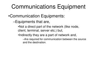
Types of IP traffic • TCP UDP Broadcast Multicast
IGMP • Multicast reserved addresses • 224.0.0.0 to 239.255.255.255 Multicast subscribers Video Server Non- subscriber
Subnets • 192.168.10.0 • 255.255.255.0 • 11000000.10101000.00001010.00000000 • 192.168.10.255 • 255.255.255.0 • 11000000.10101000.00001010.11111111
IP Subnet Division .255 .0 .1 - .254
IP Subnet Division .255 .0 .193 - 254 .1 - .62 .192 .63 .191 .64 .129 - .190 .65 - .126 .128 .127
Virtual LAN (VLAN) • What are VLAN’s? • Operate at Layer 2 • Break up broadcast domains • Create smaller, logical, network topologies • Create dedicated Virtual LANs for different services i.e. PLC & SCADA, CCTV, Corporate sever/Email access • Per-port Security levels • VLAN’s can be created in one of two ways: • Static – per port Supported in WeOS • Dynamic – MAC address allocation Not supported in WeOS
A A B B A B What are VLANs for? • Grouping parts of a network based on department, function or service. Controlling the proliferation of broadcasts throughout a network Giving flexibility to network design Providing security throughout the network
What are VLANs for? Providing security throughout the network • Default configuration • 1 Vlan • 1 Broadcast domain • Change the link port into a Vlan trunk port • 2 Vlans • 2 Broadcast domains Corporate network Industrial Network Entire network unused
How would you use VLANs? • Automation network • Corporate network • Security network
Preamble Destination MAC Address Source MAC Address Type Field 802.1Q Header Version IHL Type Of Service Total Length Identification Flags Fragment Offset TTL Protocol Header Checksum Source IP Address Destination IP Address IP Options Src port Seq number Ack Number Data Offset Reserved Dst Port Padding Flags Window Checksum Urgent Pointer Options Data from upper layers Cyclic Redundancy Check VLAN tagging + frame length • VLAN Tag information adds 4 bytes of data onto a layer 2 Ethernet frame making a maximum frame size of 1518 bytes. This information is required so that switches and routers know which VLAN this data belongs to. Ethernet at the Network layer can only process a maximum unit size (MTU) of 1500, so larger packets are segmented and then reassembled at the destination Some networking devices are unable to process frames larger than 1522 bytes (that being the size of a TCP/IP packet plus the Ethernet layer 2 encapsulation) . These devices require the tags to be removed before the frame is transmitted to them.
WeOS VLAN Concept • WeOS VLANs are built up of two elements; • Interface’s • Parameters pertaining to the VLAN configuration • Assigned Ports • The ports assigned to each VLAN
X X Inter-VLAN routing Switches cannot route between VLANs For packets to traverse different VLANs, they must be processed by a layer 3 device such as a Router or layer 3 switch
Using WeOS to configure VLANS • Practical • Introduce setup of Vlans using WeOS • Possible setup Vlan using CLI
Quality of Service (QoS) Many types of traffic will travel across a network Some of it critical , like PLC comms , or video traffic Also corporate network traffic such as e-mail, web browsing etc.
Quality of Service (QoS) Many types of traffic will travel across a network Quality of Service is a broad term applied to any technique used to allow different types of IP traffic to be treated in different ways when traversing network devices Some of it critical , like PLC comms , or video traffic Also corporate network traffic such as e-mail, web browsing etc. WeOS devices use the Priority Code Point (PCP) field within the 802.1Q (VLAN) header to enforce Quality of Service
Quality of Service (QoS) The Priority Code Point header allows eight different classes of service to be selected. Depending on the class selected problems can be avoided such as; • Jitter • Delay • Dropped Packets • Out of Order Delivery • QoS Is Required for Some Applications to work correctly • VoIP • Video Streaming • Absolutely Critical Data
Routing and Redundancy Reliable networks require Redundancy This can mean: Redundant pathways Redundant Hardware This is typically achieved by using: Redundancy Protocols Routing Protocols FRNT V0 OSPF Spanning Tree Protocol RIP BGP Virtual Router Redundancy Protocol Static Routing Rapid Spanning Tree Protocol
Routing and Redundancy Whats the difference? Redundancy Protocols Routing Protocols Determine best path for ALL traffic Decide best path for traffic on per-packet basis Discount alternative paths of communication until a fault situation occurs Always uses the best path to the destination Lower Protocol overhead Higher protocol and CPU requirements
FRNT V0 • Proprietary Westermo Redundancy Protocol • Controls topology failover • Fast (<20ms reconfiguration time)
X X X X FRNT Member FRNT Member Focal Point Member devices communicate with focal point to determine topology Focal point detects a ring is created, so it shuts down one of its interfaces which links the ring Switches continue to communicate to report status of topology If a cable fault is detected, the focal point opens its blocked interface to allow full connectivity again
STP & RSTP • Redundancy protocol which allows a switch level (layer 2) mesh topology • Network convergance times of 30 secs and 3 secs • Uses lowest bridge ID or lowest MAC address to determine Root bridge
X X X X X X Principal of root bridge Bridge ID: 8649 Bridge ID: 6039 Internet Bridge ID: 7432 Bridge ID: 4036 Bridge ID: 6696 Bridge ID: 9972 Bridge ID: 4189 Bridge ID: 5827
VRRP • Allows redundant entry/exit points to a network • Does so via a “virtual” gateway IP address which two devices control the responses to • Not to be confused with load-balancing
X X Router ID: 210 Router ID: 50 Use multicast traffic to manage response to the virtual MAC address 00-00-5E-00-01-XX 00-00-5E-00-01-XX Router with the highest VRRP ID Is the ”Master” router If the master router encounters a fault the backup router will take over
Practical Time!! • Setup FRNT ring. • Use testing tools (ping, traceroute) to verify configuration • Inspect port mirroring and wireshark
Routing • Routing occurs at layer 3 • All devices which operate at layer 3 (and above) have a routing table
Understanding a Routing table Next hop Network Metric Network next hop Metric 172.16.0.0 directly connected 0 10.0.0.0 directly connected 0 192.168.0.0 directly connected 0 192.168.10.0 192.168.0.2 1 54.19.0.0 192.168.0.2 110 0.0.0.0 172.16.0.100 0 Routing tables read sequentially from top to bottom 0.0.0.0 172.16.0.100 0 Destination address How to get there How far away it is A routing table (sometimes called a Routing Information Base or RIB) has three main parts: When a device needs to send data, it will read down through the table to find where to send it. If no exact match is found, the default gateway will be used These titles basically mean: Notes: You can tell a lot from a routing table. For instance, from this example we know that this router has three different networks configured directly on it, and it knows how to get to a further two more via a router which exists on the 192.168.0.0 network. From the metrics on the two distant networks we can tell what routing protocol is used to advertise them.