Download
1 / 29
290 likes | 430 Views
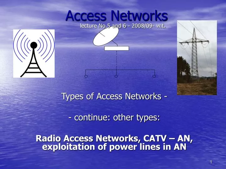
lecture No.5 and 6 - 200 8 /0 9 - w.t. Access Networks. Types of Access Networks - - continue: other types: R adio Access Networks , CATV – AN , exploitation of power lines in AN. 3.4 Radio Access Networks - RAN.

E N D
lecture No.5 and 6 - 2008/09- w.t. Access Networks Types of Access Networks - - continue:other types: Radio Access Networks, CATV – AN, exploitation of power lines in AN
3.4 Radio Access Networks - RAN • RITL – Radio In The Loop, and also other names (RLL-Radio Local Loop, WLL-Wireless Local Loop) • - general properties ofRLL - in standard- ETSI ETR 139 • radio broadcasting (LF, MF, HF), TV bands (VHF,UHF), bands of mobile teleph. networks, satellite lines, and finallytens of GHz for RR lines and broadband AN • exclusivelyradiowave networks (or with retransmission stations) or combination with cable lines • advantages: ...., disadvantages.....
Classification of radio wave media Tab. 3.4.1 Other classification – according to: services provided (teleph., data, ...) methodof sharing of information capacity ... modulation methods: ... private and public see also fig.3.4.2
RLL Fig.3.4.1General RLLReferenceModel. SS – switching system, BSC- Base Station Controller, BS – Base Station, RT- Radio termination, TE - Terminal equipment, IF – interfaces, OAM-Operation, Admin. and Maintenance functions, NMA-Network Management Agent
possibilities of including of RITL into AN: • cordless telephone • wireless AN (RLL – Radio in the Local Loop) • mobile cellular network a) user circuit CT BS b) circuits trunk TE RT BS Exchange TE RT TN c) trunk MS BS Cell Fig.3.4.2Radio wave network in AN: a) cordless telephone (CT) with individual connection, b) cordless telephone with common connection c) mobile cellular network (MS – mobile station)
Switching network SS Fig.3.4.3RLL (radio relay link) - point-to-point connection Fig.3.4.4 RLL in the transport part of AN Switching network
CT – Cordless telephone and DECT system - history: CT1, CT2, CT3 .... DECT Global network Local network Application Fig.3.4.5Generalreference model of DECT system Legend: FRT-Fixed Radio Termination PRT- Portable Radio Termination Switching network cell 1 Fig.3.4.6 : DECT architecture in Access network cell 2 cell n
DECT-continue • it is narrowband cordless access to public or private network • there exist also P-MP type of DECT and complex applications similarly to mobile networks • 3 generations • it is the base for UMTS
Broadband access systems FWA (Fixed Wireless Access) • multipoint scheme named LMDS (Local Multipoint Distribution Systems) – fixed radiowave access – the alternative option to cable AN – there are cells, devided into the sectors operated from BS by means of radiotermination, BS are connected to backbone network; mostly ATM technology, licenced bands (with guaranted QoS), without licence (so called general licence, WLAN); TDMA, FDMA and CDMA; unresistent to rain and vegetable disturbing • MMDS – (Multichannel Multipoint Distribution System) – or „wireless cable“ – utilised e.g. for TV signal distribution (DVB-C) in bands 2-3 GHz, LOS condition (Line-Of-Sight) must be satisfy for perfect receiving • WLAN (Wireles Local Area Network): - radiowave type • - IR (infra-red) type • -fixed AP (access point) connected to LAN (e.g. Ethernet) + end station (client = power adapter, transmitter, receiver, antenna, etc.), but there can be also ad-hoc networkwithout support infrastructure (stationscommunicatestraightaway - each with another) • standards IEEE 802.11, HIPERLAN, HomeRF: ...
WiFi – wireless technology, WiFi Alliance corporate mark; - for more possibilities of interconnections and connection in the frame of LAN (WLAN) • - standard IEEE 802.11b (the first utilized), 2.4 GHz band, disturbed by MW-ovens, cordless telephons and by Bluetooth; 802.11a – 5GHz – is not disturbed. (There are also other standards 802.11) • unlicencedbands, for short distances (in the building or premise, up to 11 Mbps), (they say, that without obstacles up to tens of km; up to 54 Mbps), the longer distance the less data speed, ... • WiMAX – Worldwide Interoperability for Microwave Access – system of WiMAX Forum company, this company certificates anything with WiMAX mark • wireless broadband acces within the framework of the last mile, alternative possibility to cables and DSL systems • standard IEEE 802.16 (latest 802.16-2004), transmission over the long distances, as similar technology as mobile telephony, licenc. and unlicenced spectrum • ...
WPAN (Wireless Personal Area Network) • less reach than WLAN • as suchtechnologies as Bluetooth, ZigBee, HomeRF : ...
Mobile Communications Network Supporting network Access network External systems Fig.3.4.7 Mobilecommunications system - cellular architecture, frequence planning, frequences repetition Generations: • 1. – analalogue. narrowband FM, only national systems, 450-900MHz • 2G – GSM, narrowb.TDMA, afterwardsbroadband CDMA, upstream 890-915, down 935-960MHz • 2.5G orGSM 2+ = GPRS • EDGE – between GSM and IMT-2000 • 3G - UMTS and others (IMT-2000), in the 2nd phase IP supporting network (TCP/IP protocol, radionetwork UTRAN) • “3.9 G” – LTE (Long Term Evolution) • 4G - ? http://en.wikipedia.org/wiki/UTRAN
Mobile Communications Network - continue other BS BS other MSC BS BS public fixed network other BS Legend: BS- base station Fig.3.4.8 GSM network architectureor see next page
Mobile Communications Network - continue Fig.3.4.9Functional scheme of GSM network
Mobile Communications Network - continue Fig.3.4.10 GSM more detailed
GPRS (General Packet Radio Service) – mobile data service, accessible for GSM users (and for IS-136 mobil users) – for WAP services (Wireless Application Protocol), SMS, MMS and e-mail a www- access „2,5G“ UMTS – Universal Mobile Telcom. System – 3G mobile system, W-CDMA, access to web pages and to other data services, up to 14Mbps historical application: paging – unidirectional radio systems (transport of data only in the direct to TE)– for both smaller private, but also greaterpublic areas
Mobile Communications Network - continue Radiowave Access Systems satellites Fixed Access Systems cellular networks WLAN Support network WPAN WLL radio and TV broadcasting Fig.3.4.11 One of possible ideas of 4G network architecture concept - interoperability of several types of radiowaves networks
Radio-relay links - RRL - fixed access point + mostly also fixed user terminal (point-to-point) according to link length system each-to-another purpose - portable - fixed Fig.3.4.12: Classification of RRL systems (Radio Relay Link) - data speeds from E1 (2Mbps) up to STM1(155Mbps), 40-60 km, frequency bands and frequency channels, H/V polarizations of neighbour channels, QAM channel modulation
core networks – up to 11 GHz access networks – above 11 GHz notification notification Tab. Frequency band for RRLs (point-to-poit)
Bandwidth Digital stream Nuber of states - modulation XPIC – additional circuits for interference suppressing by utilizing different polarizations of waves of the same frequency Tab. Bandwidths in RRLs and possible combinations of STMdig. streams Fig.: Example: RR channels in band 6U
Satellite networks - advantages, disadvantages - VSAT technology(Very Small Aperture Terminal – for both narrowband and broadband data (Internet, VoIP a video) LEO: Argos, Orbcomm, Iridium, Teledesic, Globalstar, Skybridge GEO: Thuraya (, Inmarsat (maritime - communications), cca 36000km above equator Fig.3.4.13Examples of shapes and dimensions of several satellites orbit types
specifications: • DVB-Cdig. signal, MPEG-2 compress encoding, resp. MPEG-4 AVC (H.264) • 4 or 5 dig. channels in previous 1 analogue onecarrier is modulated by transport stream by means of QAM • central node – previously with distribution role – now is transformed for bidirectional transport (interactive services) – down 65 -850 MHz with 8 MHz per channel; up 5-65 MHz (in USA 42-850 MHz / 5-42 MHz and 6 MHz channels) • possibility of POTS – the main station must be interconnected with PSTN (see the next figure) • needed modernization of whole network (several hierarchy level of network,amplifiers, optical sections, O/E convertors, freq. splitters,....) • -comunications standards based on IP protocol(Ethernet-frameswith variable word length, resp. ATM technology): • DOCSIS - Data Over Cable Service Interface Specification • = international standard for communications via CATV • (DOCSIS 3.0) – is also for cabel modems • DVB/DAVIC Euromodem – standard developed in Europe (by ETSI)
aerial (antennas) system Main Station – there are antenna combiners, convertors , amplifiers, splitters centr.office splitter distrib.node primary optical PON section splitter tap / coupler - user splitter (tap?) / coupler - user wall outlet splitter (or band separator) of down- and up- directions secondary – coaxial section 2-way amplifier Fig.3.5.1Architecture of CATV- AN with optical network in the primary segment (primary level) the components of distribution system see e.g. in: http://www.blondertongue.com/distribution/Distribution.pdf
HF splitter CATV subscriber line CATV modem MAC – Medium Access Controll interface (Ethernet, USB, PCI) 64/256-QAM demodulator, error correction control (CPU) telephone subscriber line telephone modem return channel realization in the case of 1-directional CATV network Fig.3.5.2Functional scheme of cable modem and its implemenation into network (it can be integratedin Set-Top-Box) – upstream is realized by telephone line
3.6 PLC - Power Line Communication or: PDSL- Power DSL - utilizing of power lines in the role of broadband AN • advantages:
Base unit Internet customer customer HF LF User terminal Power transformer station HF LF LAN kWh 4 x 400 V customer Fig.3.6.1Principle of using power network for broadband (BB) access • 2-phase wires for providing of BB services • LF, HF filters • high security required
Tab.3.6.1 : Frequence bands previously permited by european norm for communications • but – for PDSL – there are allowable bands up to tens MHz (the larger distance the less transported frequencies) • development in area e-m compatibility and mutual interferences of different tel-com systems and disturbing by power network (there are stated some treshold values… )
IPTV and Internet via convenience outlet (in the frame of home network)- architecture: • Internet connecting • router (or DSL modem) connected to both Internet and power network • adaptors of Powerline technologyconnected to outlets in residence (behind transformer station, in the same phase circuit) • in the reach of 101 m data speeds up to 200 Mbps • undesirable: overvoltage defence (protect) and filters (!)