Download

1 / 125
1.26k likes | 1.46k Views
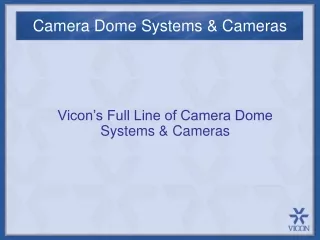
Surveyor Series Dome Cameras. Technical Support. 1-800-34-VICON (1-800-348-4266) 8:00 AM – 6:30 PM Eastern Time Monday through Friday 1-800-645-9116, Extension 877 After Hours and Weekends or Holidays. Other Numbers. Website http://www.vicon-cctv.com

E N D
Surveyor Series DomeCameras
Technical Support 1-800-34-VICON (1-800-348-4266) 8:00 AM – 6:30 PM Eastern Time Monday through Friday 1-800-645-9116, Extension 877 After Hours and Weekends or Holidays
Other Numbers • Website http://www.vicon-cctv.com • FTP Site ftp://ftp.vicon-cctv.com • Parts Department 1-800-645-9116, Ext 369 • Service Department 1-800-645-9116, Ext 384
Data Communications There are three major types of Serial Communication Standards
Data Communications RS-232 • Unbalanced Circuit (single conductor plus ground reference) • Short Distances (typically <50 feet) • Used in Low Noise Environments • Bi-Polar Signal (voltage levels swing + and -) • Point-to-Point Communications
Data Communications • RS-422 • Balanced Circuit (two signal conductors plus ground reference) • Long Distances (typically ~4000 feet) • Excellent Noise Immunity • Signal Levels of 0.0 vdc and +5 vdc • Point-to-Point Communications
Data Communications RS-485 • Balanced Circuit (two signal conductors plus ground reference) • Long Distances (typically ~1000 feet) • Excellent Noise Immunity • Signal Levels of 0.0 vdc and +5 vdc • Multidrop Communications (Typically 32 Nodes)
Data Communications • Within each standard, there are communications types
Data Communications • Simplex This is a uni-directional form of communications. Duplex This is a bi-directional form of communications.
Data Communications • Within the Duplex mode are two further sub-divisions: • Full Duplex – • - This mode permits simultaneous bi-directional communications. • Half-Duplex – • - This mode is bi-directional also, but only one direction at a time.
Data Communications • Vicon uses both Simplex and Half-Duplex Communications • Keypads must use Half-Duplex. • Receiver-Drivers and Dome Cameras • can use either Simplex or Half-Duplex
Data Communications • Data Signal Names used by Vicon are Command and Response. • Command – this signal is generated by a CPU and is sent to a peripheral device, either a Keypad or a Camera Receiver-Driver. • Response – This signal is generated by a peripheral device and sent to the CPU as an answer to a Command from the CPU.
Data Communications • To comply with the RS422 balanced circuit, there is a Positive (+) and Negative (-) side of the signal. • Vicon uses the terminology “Command +” and “Command –”, as well as “Response +” and “Response –”.
Data Communications • Starting at the CPU, the signal lines would be called Command Out + and Command Out -. They will connect to the peripheral device to Command In + and Command In -, respectively. • At the peripheral device, the signal lines would be called Response Out + and Response Out -. They will connect back to the CPU to Response In + and Response In -, respectively.
Data Communications Connection Rules: • Command always connects to Command • Response always connects to Response • + signals always connect to + signals • - signals always connect to – signals • Inputs connect to Outputs • Outputs connect to Inputs
Data Communications • Some types of equipment, fiber optic modules for instance, use connection terms such as Data In + or Data Out +. • In these cases, Data Out + would be the same as Command Out + or Response Out + (depending on the direction of signal flow).
Data Communications • Data Cabling • For data wiring of peripheral devices, Vicon recommends the • use of a dual-pair, twisted, individually shielded wire meeting the specifications of one of the cable types listed below: • Belden™ 8723 • West-Penn Wire ™ D510 • Alpha Wire ™ 2466C • Note: these part numbers are for PVC jacketed wire. Check manufacturer’s catalog for Plenum versions if local codes dictate.
Data Communications • Questions?
Surveyor Models • Model Numbering Scheme • S2000 – RW23 • Camera Series • Type • Use • Lens Type
Surveyor Models • Model Numbering Scheme • Camera Series: S2000 (earlier series) • SVFT (current series) • Type: M (Monochrome) • C (Color) • R (Day-Night
Surveyor 2000 Models • Model Numbering Scheme • Use C (Indoor Ceiling Mount) • P (Indoor Pendant Mount) • W (Outdoor) • Lens Type 18 X • 22 X • 23 X
Surveyor 2000 Models • Models • S2000-CC22 Indoor/In-Ceiling, • S2000-CP22 Indoor/Pendant, • S2000-CW22 Outdoor • S2000-RC23 Indoor/In-Ceiling, Day-Night • S2000-RP23 Indoor/In-Ceiling, Day-Night • S2000-RW23 Outdoor, Day-Night • S2000-RW-PR Indoor-Outdoor Pressurized
Surveyor VFT Models • Models (all Color Cameras) • SVFT-C22 Indoor/In-Ceiling • SVFT-P22 Indoor/Pendant • S2000-W22 Outdoor • S2000-C23 Indoor/In-Ceiling, Day-Night • S2000-P23 Indoor/In-Ceiling, Day-Night • S2000-W23 Outdoor, Day-Night • S2000-PR-23 Indoor-Outdoor Pressurized
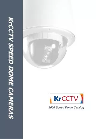
Similarities S2000 SVFT
Similarities Externally, it is difficult to distinguish between the two models.
Similarities Software between the two is almost identical from the user and programmer standpoints.
Differences • Mechanically, the drive mechanisms and housings are totally different. • The SVFT drive assembly cannot be installed in an S2000 housing and the same is true that the S2000 drive assembly cannot be installed in an SVFT housing.
Differences S2000 SVFT
Differences (S2000) Connections are made directly to the Drive Assembly PCB
Differences (SVFT) Connections are made directly to the PCB located in the housing.
Installation SVFT-UWMUniversal Wall Mount
Installation SVFT-WM Wall Mount
Installation SVFT-UPMUniversal Parapet Mount
Installation SVFT-URMUniversal Roof Mount
Installation TB3 Comm In J3 Comm In J1 24VAC Power S2 Communications SettingsS1 Camera Address J1 Video Output J2 Alarm Inputs S2000 Interconnect Board
Installation S2000 DipswitchesS2 Communications TypeS1 Camera Address
Installation The Customer Interface Board pivots for access to the rear side. It can also be removed from the housing without tools. SVFT Interconnect PCB