Download
1 / 22
220 likes | 349 Views
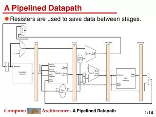
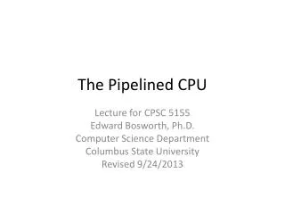
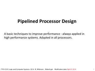
Pipelined Electronics. Design Concept: Low Cost. Add-on modules. Sub-detector I/F User-defined module for analog part only. Minimizing the development cost. Readout CPU Commercially available PMC module. No hardware development cost. Common pipelined-readout platform (motherboard)

E N D
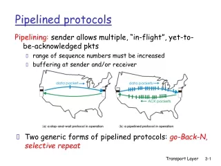
Pipelined Electronics Super B Factory Workshop Detector (DAQ/Computing) Parallel
Design Concept: Low Cost • Add-on modules • Sub-detector I/F • User-defined module for analog part only. • Minimizing the development cost. • Readout CPU • Commercially available PMC module. • No hardware development cost. • Common pipelined-readout platform (motherboard) • Generalized DAQ software.
Common Readout Platform: COPPER Form factor = VME 9U Sub-detector I/F slot4 Pipeline FIFO (1MB) 4 PMC slot3 32-bit local bus 32-bit 33MHz PCI bus Local-PCI bridge FastEthernet I/F VME I/F PMC Processor Sub-detector I/F Sub-detector I/F Sub-detector I/F Trigger • Data transfer on COPPER • measured >65 MB/s. • >30 kHz L1 rate @ 1.6 kB/ev. • Data size corresponds to typical SuberKEKB DC/COPPER. Sub-detector I/F Generic PMC slot On-board Ether
PCI Mezzanine Card 100% compliant with the PCI. Suitable for high density applications. Many commercial products are available: Ethernet cards, GbE cards, memory modules, CPUs, etc. RadiSys EPC-6315 PentiumIII 800 MHz w/ 512 MB main memory. 32-bit 33/66 MHz PCI bus interface. PMC / PMC Processor PCI NIC PMC NIC Contains Linux kernel image
Sub-Detector I/F: FINESSE • FINESSE: 18676 mm2 daughter card on the COPPER • Receives and digitizes sub-detector analog signals. • Holds the digitized signals for the level-1 trigger latency. • Outputs the data to the COPPER. • Some FINESSE variations • TDC • ADC • TDC “tandem”
t1 t2 T(Q) tSTOP t Q-to-T conversion TDC & ADC at the same time, simplifying the readout scheme. SuperBelle CDC Readout: QTC+TDC • QTC: charge to time conversion drift charge to sense wire event L1-trigger Q 0 tDRIFT t • t1 = drift time • t1 – t2 = drift charge 9U-VME sized QTC module with LeCroy MQT300 QTC chip
AMT-3 TDC chip SuperBelle CDC Readout: QTC+TDC • TDC: time to digital conversion Requirement FINESSE with AMT-3 TDC chip (originally designed for ATLAS)
AMT-3 TDC Chip • Up to 17 bit timing measurement: coarse + fine counters • Pulse edge timings: coarse + fine • Trigger timings: coarse • Trigger matching • Only the edges associated to Level-1 trigger are output. • Level-1 pipeline provided (256 edges) Coarse counter: 13-bit bunch crossing counter (40MHz @ LHC) Fine counter: additional 4-bit time memory cell • SuperBelle system clock • Bunch crossing rate: LHC = 40 MHz,KEKB = 508 MHz. • We choose SuperKEKB system clock= 42.33 MHz = 508/12.
AMT-3 output Trigger matching AMT-3 Readout FIFO (64 edges) trigger latency (~5ms?) Level-1 pipeline FIFO (256 edges) edge search Trigger matching time 24 OK NG collision L1 trigger Channel buffer (4 edges) Channel buffer (4 edges) Trigger timing FIFO (8 events) Channel buffer (4 edges) 24-channel inputs Level-1 trigger inputs AMT-3 TDC Chip – Cont’d
DATA DREADY SCLK: 42.3 MHz to COPPER AMT-3 FPGA w/ FIFO BUSY No further trigger of AMT-3 • No hardware output indicating FIFO full • Unexpected data loss is only notified by an “error flag” in the next event output. • Readout “readout FIFO” of AMT-3 quickly
AMT-3 L1-Pipeline Depth • Less depth: 256 edges shared by 24-input channels • LeCroy TDC (we’re currently using): 16 edges / each channel. • Is it sufficiently large? MC simulation is needed. • MC parameters – Assuming SuperBelle drift chamber • # of input channels: 24 • Random wire hit: 100 kHz (Poisson distribution) • Level-1 trigger rate: 50 kHz (Poisson distribution) • # of gen. words per wire hit: 2 for signal edges + additional for noise • Level-1 trigger latency: 5 ms Extreme case
Extrapolation assuming the right side slope unchanged. Extrapolate … = ~104 “Toy” MC Simulation: Buffer Usage Very preliminary 13.7 s 1.37 s 137 ms 13.7 ms FIFO/AMT-3 won’t get full before O(105) sec. Entries / 1 edge FIFO full point Level-1 pipeline usagesampled at every clock [edges]
TDC FINESSE with AMT-3 • Block diagram of TDC FINESSE (not finalized yet) Xilinx Spartan-3 FIFO Dataformatter AMT-3 Sub-detector Triggerreply logic FIFO-fullmonitor COPPER event FIFO COPPER FIFO full Busygenerator Local-busI/F 42.3MHzclock Trigger busy Local bus (A7D8) Level-1 trigger
Measured pulse width dist. ch id. (ch = 0x0b) 1: leading edge pulse width peak = 251 ns rms = 0.93 ns 0: trailing edge content tag (0x3 = edge data) 17-bit edge timing The First AMT-3 Signal on COPPER COPPER Pulsegenerator NIMECLconverter FINESSE CPU AMT-3 4.2 ms 250 ns @ ch 0x0b [Readout data] w#1: 00111010010111011110110110000110 w#2: 00111010010110011110111011011010 w#1: 00111010010111011110110110000110 w#2: 00111010010110011110111011011010
Future Plan • Short term (-Jul.): System test • TDC resolution study with test input pulses. • Investigation of FIFO full behavior of AMT-3. • Stability tests: stability against random trigger, long-run stability, etc. • Software development: device driver, readout software, etc. • Middle term (Aug.-Nov.): First step integration to Belle DAQ (EFC) • EFC is the smallest sub-detector (total = 320 ch). • EFC has two alternative readout paths (CDAQ + EFC own): failsafe and easier crosscheck. • Long term (Dec.-): CDC readout with COPPER based system
VME crate FASTBUS COPPER3 TDC3 PC VxWorks Ethernet switch COPPER3 TDC3 TDC “Tandem”FINESSE COPPER TDC TDC TDC TDC First Step Integration into Belle DAQ EFC =Extreme Forward Calorimeter • Replace Belle EFC DAQ with COPPER BackwardEFC ForwardEFC 160 ch EB 160 ch Local STOR
Summary • We have developed module-structured system for SuperBelle readout consisting of COPPER boards and FINESSE cards. • The QTC and TDC will be employed to readout SuperBelle CDC data. • We use AMT-3 TDC chip. The TDC FINESSE card with the AMT-3 has been developed. • Level-1 pipeline depth in the AMT-3 is examined by MC simulation. • We have observed the AMT-3 is correctly digitizing the input pulses. • The first step integration of the COPPER system into the Belle DAQ is planned in this August using EFC.
TDC “Tandem” FINESSE • LeCroy TDC: 6 connectors • COPPER: 4 FINESSE slots • To use present analog cables… • We’ve made a ‘tandem-FINESSE’module equipped with 3 connectors. • Channel density • 48 ch / tandem-FINESSE. • Same as present LeCroy TDC. 2 16 ch AMT-3 8 ch 8 ch AMT-3 16 ch Tandem-FINESSE
Readout PC and Event Builder Present event builder copper0 copper1 GbE GbE GbE Switching hub … 100 Base-T copper5 Readout PC Data transferperformance • Readout PC: • CPU : Intel Dual Xeon 2.46 GHz • OS : RedHat9(2.4.18-20smp) Faster readout PC and/or software tuning are requested for SuperBelle use.
Calibration Run • Calibration run • Daily detector calibration with test pulse and/or test trigger. • Readout PCs should take responsibility to collect data • O(100) COPPERs / sub-detector 6 readout PCs Event building mechanism is needed for calibration run.
Compact Flash Boot up procedure is well established. Distribution of updated software to all CF cards is non- trivial. Write access to CF card shortens the card lifetime. CF card is getting out of date. Network boot Distribution of updated software to all CF cards is easy. We have no established method yet to boot-up EPC-6315 from network. Boot-PC farm serving multiple boot requests must be developed. It is never trivial. CPU Boot-up Mechanism
Run Control private network fbdaq copper0 copper1 … NSM Master copper5 NSM Gateway Readout PC (l0efc) NSM NSM or other mechanism To avoid increase of NSM nodes, we put NSM gateway (like SVD2).