Download
1 / 18
180 likes | 373 Views
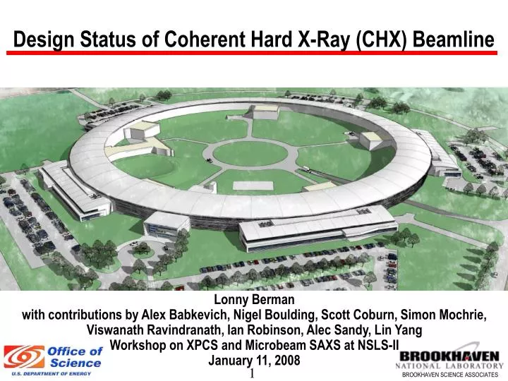
Design Status of Coherent Hard X-Ray (CHX) Beamline. Lonny Berman with contributions by Alex Babkevich, Nigel Boulding, Scott Coburn, Simon Mochrie, Viswanath Ravindranath, Ian Robinson, Alec Sandy, Lin Yang Workshop on XPCS and Microbeam SAXS at NSLS-II January 11, 2008. Outline.

E N D
Design Status of Coherent Hard X-Ray (CHX) Beamline Lonny Berman with contributions by Alex Babkevich, Nigel Boulding, Scott Coburn, Simon Mochrie, Viswanath Ravindranath, Ian Robinson, Alec Sandy, Lin Yang Workshop on XPCS and Microbeam SAXS at NSLS-II January 11, 2008
Outline • Beamline Requirements and Specifications • Beamline Design • 2.1 Beamline layout • 2.2 Insertion device • 2.3 Front end • 2.4 White beam components • 2.5 Specialized beam conditioning optics • 2.6 Endstation • Schedule • Summary • Questions for Discussion
1. Beamline Requirements and Specifications • Coherent flux to supply photons to an endstation for x-ray photon correlation spectroscopy (XPCS) and small angle x-ray scattering (SAXS) with possibility of coherent x-ray diffraction (CXD) strictly at low q • Energy range 7-20 keV using either tunable silicon double crystal monochromator or “pink beam” reflected from mirror • At 8 keV, coherent flux using a Si mono is 6x10¹² ph/sec, and transverse coherence lengths at 25 m from the source are 819 µm vertically and 65 µm horizontally (Ch. 3 of NSLS-II CDR) • Stability • Parasitically fluctuating signals contaminate XPCS time autocorrelation analysis • Fixed secondary horizontal source intended to improve stability for these experiments • Long XPCS/SAXS station • “Smart” area detectors likely to have larger pixels than today’s • While mainly for XPCS, can also accommodate state-of-the-art SAXS experiments
2. Beamline Design: Original Conceptual Design The original design embodied two independent beamlines viewing the same undulator source, with the beam split into two coherent portions in the FOE using apertures and mirrors, deflecting these two beams to separate beamlines (with subsequent monochromatization and focusing). The shorter beamline would be devoted mainly to XPCS but could accommodate some CXD (strictly low-q applications of hard x-ray coherent beams) and the longer beamline would be devoted mainly to CXD but could accommodate some XPCS (strictly high-q applications of hard x-ray coherent beams). See http://www.bnl.gov/nsls2/project/CDR/ portions of chapters 3 and 11, prepared by Alec Sandy, Simon Mochrie, and Ian Robinson.
Beamline Design: Recent Conceptual Design The original conceptual design was elaborated further through a more detailed advanced conceptual design, prepared in collaboration with Oxford-Danfysik. After it was completed, the scope of this beamline was reduced, whereby the longer (high q) beamline was taken out. No changes were made to the design of the surviving shorter (low q) beamline as a result. All of the infrastructure inside the building to re-accommodate the longer beamline (e.g. space in the FOE for the optical components, beam transit section to accommodate the split beams) was preserved.
2.1 Overall Beamline Layout endstation enclosure This is the advanced conceptual design for the surviving shorter beamline. See http://www.bnl.gov/nsls2/project/PDR/2-ExFac-Ch_003_CHX_1-9-08.pdf XPCS/SAXS endstation 50 m from source monochromator enclosure FOE
Beamline Superposed on Floor Plan X25 beamline viewing 3-pole wiggler source (shown for size comparison) coherent hard x-ray beamline 5 m
Conceptual Design of Components in FOE • Secondary source or pinhole in the FOE • Small horizontal-bounce mirror used to extract coherent fraction of the beam (in the horizontal) • For the project, just one beamline will be constructed, designed in a way to accommodate a second beamline later, if desired CHX FOE Beam Splitting Concept - Plan View Pink beam (for later longer beamline) White beam (WB) Hi-pass filter Shutter Slit ½ Slit Mirror = secondary source or pinhole 12 mrad WB Stop Power-reducing aperture Pink beam (for project beamline)
Monochromator and Endstation Layout endstation enclosure monochromator enclosure
2.2 Insertion Device • U19 (now U20) undulator preferred (unless U14 exists) • High beta straight section • Brighter than APS UA by a factor of 7 at 9 keV under these conditions (U19, high beta); coherent flux is directly proportional to brightness • Useful upgrade is to add a second undulator in-line 20 m 30 m coherence-defining aperture at sample = 30 µm secondary source = 67 µm undulator source >~ 212 µm Filling of secondary aperture for beamline can only be accomplished if undulator source width >~ 212 µm, leading to the preference for a high beta straight section.
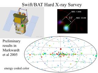
Undulator Spectra NSLS-II U19 high beta NSLS-II U19 low beta
2.3 Front End Layout • Front end must include motorized adjustable apertures • Will typically be closed down to an opening no greater than 100 µrad x 100 µrad • Thereafter, a beam of up to 20 µrad x 20 µrad will be extracted for the beamline
2.4 White Beam Components • Water-cooled silicon mirror and monochromator preferred for the beamline, to avoid vibrations associated with a cryo-cooling system (maximum power density is ~100 W/mm2 but maximum power in 20 µrad x 20 µrad is ~30 W) • Strategy embodies splitting absorbed power between mirror and monochromator • Finite-element analyses and Shadow ray tracing were carried out for various cases, involving use of one and two undulators, operating at low K and at high K, at 9 keV • These indicate that water-cooled optics will be acceptable; the slope errors (<1 µrad rms for mirror [10 W], <4 µrad rms for monochromator [6 W], using one undulator) may be noticeable, may have to be compensated using downstream focusing optics • Pink beam capability is preserved into the endstation if desired
2.5 Specialized Beam Conditioning Optics • Focusing optics will sometimes be used in the endstation, just before the experimental apparatus • A vertical focusing mirror (or kinoform lens) is desired to reduce the vertical coherence length in order to match the horizontal coherence length
2.6 Endstation mirror or refractive lens sample chamber apertures 10 m flight path The highest q accessible at 12 keV and 10 m sample-to-detector distance is ~0.15Å-1, although a higher q range can be accessed on one side by offsetting the flight tube and detector. heavily pixellated area detector with on-board correlator electronics
4. Summary • We have a detailed beamline design which meets the requirements for a state-of-the-art XPCS/SAXS experimental program • We developed detailed cost and schedule estimates that will deliver the required beamline performance within the constraints of the project • The beamline extracts a coherent portion of the beam radiated by an undulator • A deflecting mirror is used to deflect and deliver the beam to a beamline devoted to XPCS/SAXS • When operating, this beamline will deliver world-leading capability and open heretofore unexplored areas
5. Questions for Discussion • CD-2 review committee encouraged consideration of removal of white beam mirror and implemention of cryogenic cooling of monochromator – impact on coherence? Nano-CAT at APS is doing this (implementing cryogenic cooling instead of water). • No white beam mirror means no pink beam – still needed? • Is it still important to have a secondary source defined in the FOE? In this context, the beam stability requirements are 0.2 µm position stability (vertical and horizontal), 0.1 µrad vertical angle stability, 1 µrad horizontal angle stability. A lot of info at http://www.bnl.gov/nsls2/workshops/Stability_Wshop_4-18-07.asp (NSLS-II Stability Workshop and Task Force Report). • Would a low beta straight section be preferred? • Should a wide angle scattering capability be provided?