Download
1 / 28
380 likes | 762 Views
Heat Exchanger Network Synthesis, Part III. Ref: Seider, Seader and Lewin (2004), Chapter 10. Instructional Objectives. This Unit on HEN synthesis serves to expand on what was covered in the last two weeks to more advanced topics. Instructional Objectives - You should be able to:

E N D
Heat Exchanger Network Synthesis, Part III • Ref: Seider, Seader and Lewin (2004), Chapter 10
Instructional Objectives • This Unit on HEN synthesis serves to expand on what was covered in the last two weeks to more advanced topics. • Instructional Objectives - You should be able to: • Extract process data (from a flowsheet simulator) for HEN synthesis • Understand how to use the GCC for the optimal selection of utilities • Have an appreciation for how HEN impacts on design
Data Extraction Process analysis begins with the extraction of “hot” and “cold” streams from a process flowsheet Required: • The definition of the “hot” and “cold” streams and their corresponding TS and TT • CP for each stream is either approximately constant or H=f(T).
Mixing: Consider as two separate streams through to target temperature. • Splitting: Assume a split point wherever convenient. What is considered to be a stream ? • In general: Ignore existing heat exchangers
Example – Dealing with Real Systems • Toluene is manufactured by dehydrogenating n-heptane. • Furnace E-100 heats S1 to S2, from 65 oF to 800 oF. • Reactor effluent, S3, is cooled from 800 oF to 65 oF. • Install a heat exchanger to heat S1 using S3, and thus reduce the required duty of E-100. • Generate stream data using piece-wise linear approximations for the heating and cooling curves for the reactor feed and effluent streams. • Using the stream data, compute the MER targets for Tmin = 10 oF.
Equivalent, piece-wise flowing heat capacity: Example – Dealing with Real Systems • Heating of liquid • Heating of vapor • Evaporation of n-heptane
Equivalent, piece-wise flowing heat capacity: Example – Dealing with Real Systems • Cooling of vapor • Condensation
Equivalent, piece-wise flowing heat capacity: Example – Dealing with Real Systems
Example – Dealing with Real Systems • (b) MER Targeting:
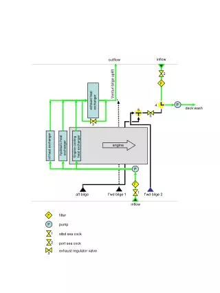
Class Exercise 7 a) Extract data for hot and cold streams from the flowsheet below.b) Assuming Tmin = 10o, compute the pinch temperatures, QHmin and QCmin.c) Retrofit the existing network to meet MER.
Class Exercise 7 - Solution • Tmin = 10 oC
This defines: Cold pinch temperature = 140oC QHmin = 100 kW QCmin = 166 kW Class Exercise 7 - Solution (Cont’d) • Tmin = 10 oC
Heat Integration in Design • The Grand Composite Curve • An enthalpy cascade for a process is shown on the right. • Note that QHmin = QCmin = 1,000 kW • Also, TC,pinch = 190 oC
The Grand Composite Curve (Cont’d) • The Grand Composite Curve presents the same enthalpy residuals, as follows: • Minimum external heating, at 310 oC • Internal heat exchange • TC,pinch • Internal heat exchange
The Grand Composite Curve (Cont’d) • Alternative heating and cooling utilities can be used, to reduce operating costs:
Example: • GCC: The Grand Composite Curve (Cont’d)
GCC Example (Cont’d) • Possible designs using CW and HPS: • Umin = 4 + 2 – 1 = 5 • How many loops? • Does this design meet Umin ? If not, what is the simplest change you can make to fix it?
GCC Example (Cont’d) • Returning to the GCC:
GCC Example (Cont’d) • Possible designs using CW, BFW, LPS and HPS:
Heat Integration in Design • Heat-integrated Distillation • Distillation is highly energy intensive, having a low thermodynamic efficiency (as little as 10% for a difficult separation), but is widely used for the separation of organic chemicals in large-scale processes. • Thermal integration of columns can be done by manipulation of operating pressure. • Note: Qreb Qcond for columns with saturated liquid products. • Need to position column carefully on composite curve
(a) Exchange between hot • and cold streams • (b) Exchange with cold streams Heat-integrated Distillation (Cont’d) • Option A: Position distillation column between hot and cold composite curves:
Heat-integrated Distillation (Cont’d) • Option B: • 2-effect distillation: (a) Tower and heat exchanger configuration; (b) T-Q diagram.
Heat-integrated Distillation (Cont’d) • Option B: Variations on two-effect distillation: • (a) Feed Splitting (FS) • (b) Light Split/forward heat integration (LSF) • (c) Light Split/Reverse heat integration (LSR).
(c) reboiler flashing • (a) heat pumping • (b) vapor recompression Heat-integrated Distillation (Cont’d) • Option C: Distillation configurations involving compression: • (a) heat pumping • (b) vapor recompression • (c) reboiler flashing
All 3 configurations involve the expensive compression of a vapor stream. May not be cost-effective except where pressure changes required are small. Example: separation of close-boiling mixtures For further reading: Smith, R., “Chemical Process Design and Integration”, Wiley, 2005, Chapter 11. Heat-integrated Distillation (Cont’d) • Option C: Distillation configurations involving compression: • (a) heat pumping • (b) vapor recompression • (c) reboiler flashing
Heat Integration - Summary • Data Extraction • Getting data for HEN synthesis from material and energy balances (i.e., from simulator) • Heat Integration in Design • Use of Grand Composite Curves for selection of utilities • Options for heat-integrated distillation