Download
1 / 13
130 likes | 222 Views
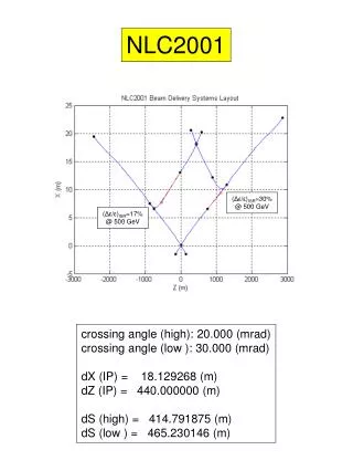
Beam Loss in the Extraction Line for 2 mrad Crossing Angle A.Drozhdin, N.Mokhov, X.Yang. February 28, 2006 A.Drozhdin, N.Mokhov, X.Yang. Beta and dispersion calculated by STRUCT in the extraction line with real extraction trajectory and QF1 multipoles from KoL to K9L.

E N D
Beam Loss in the Extraction Line for 2 mrad Crossing AngleA.Drozhdin, N.Mokhov, X.Yang
February 28, 2006 A.Drozhdin, N.Mokhov, X.Yang Beta and dispersion calculated by STRUCT in the extraction line with real extraction trajectory and QF1 multipoles from KoL to K9L
February 28, 2006 A.Drozhdin, N.Mokhov, X.Yang Disrupted beam (file beam1 from cs21_hs) without vertical offset at IP (red), 3 sigma beam (blue) and beamstrahlung photon (file photon.dat from cs21_hs) beam (green) are printed out at QD0 exit, SD0 exit, QF1 exit, QEX1 entry, QEX1 exit, QEX1B exit, SEX1 exit, and BHEX1 exit in the order of top to bottom and left to right.
February 28, 2006 A.Drozhdin, N.Mokhov, X.Yang Disrupted beam (file beam1 from cs21_hs) without vertical offset at IP (red), 3 sigma beam (blue) and beamstrahlung photon (file photon.dat from cs21_hs) beam (green) are printed out at QEX3 exit, QEX4 exit, QEX 5 exit, BHEX2 exit, BYENE exit,BHEX3 exit, DUMP entry, and DUMP exit in the order of top to bottom and left to righ.
February 28, 2006 A.Drozhdin, N.Mokhov, X.Yang Disrupted beam (file beam1 from cs21_dy100_hs) with vertical offset at IP of 100 nm (red), 3 sigma beam (blue) and beamstrahlung photon (file photon.dat from cs21_dy100_hs) beam (green) are printed out at QD0 exit, SD0 exit, QF1 exit, QEX1 entry, QEX1 exit, QEX1B exit, SEX1 exit, and BHEX1 exit in the order of top to bottom and left to right.
February 28, 2006 A.Drozhdin, N.Mokhov, X.Yang Disrupted beam (file beam1 from cs21_dy100_hs) with vertical offset at IP of 100 nm (red), 3 sigma beam (blue) and beamstrahlung photon (file photon.dat from cs21_dy100_hs beam (green) are printed out at QEX3 exit, QEX4 exit, QEX 5 exit, BHEX2 exit, BYENE exit,BHEX3 exit, DUMP entry, and DUMP exit in the order of top to bottom and left to righ.
February 28, 2006 A.Drozhdin, N.Mokhov, X.Yang Disrupted beam (file beam1 from cs21_dy100_hs) with vertical offset at IP of 100 nm (green) and synchrotron radiated photons (red) from the disrupted beam are printed out at QD0 exit, SD0 exit, QF1 exit, QEX1 entry, QEX1 exit, QEX1B exit, SEX1 exit, and BHEX1 exit in the order of top to bottom and left to right.
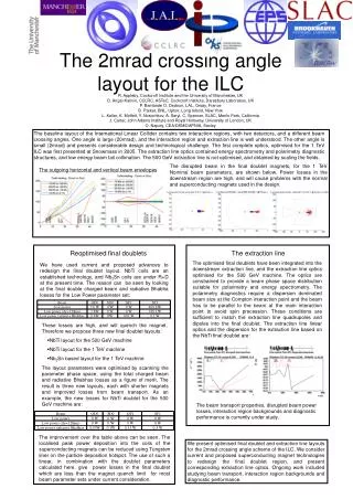
February 28, 2006 A.Drozhdin, N.Mokhov, X.Yang Particle loss distributions for beam with vertical offset at IP of 100 nm (file tail1 from cs21_dy100_hs) for increased aperture of beam line. As shown in the first two lines, aperture increase up to R=260-300~mm does not help to reduce electron loss in the region downstream of the last chicane below 1.5 KW/m. The only way to reduce heat load to the magnets is to place shadow collimators and synchrotron radiation masks between all magnets. Heat load to these collimators (bottom, left) is very high - 5-20 KW/m. There is no primary particle loss at the magnets (bottom, right). Heat load from the secondary flux will be calculated using MARS.
February 28, 2006 A.Drozhdin, N.Mokhov, X.Yang Synchrotron radiation loss distribution along the extraction line for beam with vertical offset at IP of 100 nm (file beam1 from cs21_dy100_hs). The total synchrotron radiation power from the beam is 0.76 MW. This is 3.4% of the beam power. Synchrotron radiation load to the beam line elements can not be reduced by increasing of aperture (see top line). Photons are intercepted by the aperture at any case because they do not follow the trajectory of the beam line as the beam does. The only way to reduce heat load from synchrotron radiation to the magnets is to place synchrotron radiation masks with less aperture between magnets. Photon losses in the chicane region to the masks are approximately equal to 5-10 kW (bottom line). There is no primary photon loss at the magnets at this case.
February 28, 2006 A.Drozhdin, N.Mokhov, X.Yang Particle (left) and photon (right) loss distributions for line with shadow collimators and synchrotron radiation masks between all magnets. Heat load to these collimators is very high - 10-30 KW/m. There is no primary particle and photon loss at the magnets (see second and bottom lines).
February 28, 2006 A.Drozhdin, N.Mokhov, X.Yang An example of typical synchrotron radiation loss distributions across the synchrotron radiation mask.
February 28, 2006 A.Drozhdin, N.Mokhov, X.Yang Vertical-longitudinal view of energy deposition per train in first millimeters of the left jaw (left) and transverse view of energy deposition per train at shower maximum (z=4 cm) (right).
February 28, 2006 A.Drozhdin, N.Mokhov, X.Yang Transverse view of residual dose at the upstream end of collimator HCOLL3 irradiated for 30 days 20% average intensity and cooled for 1 day; to convert to a full intensity one needs to multiply this plot by 5. Conclusions: - total power dissipation in collimator HCOLL3 is 16~kW; - peak temperature rise is dT=20C per train; - estimated steady state temperature can be about 200C or higher, strongly dependent on cooling system (it is desirable to have a few times lower); - activation on the upstream end and on the beam-side (jaws) reaches 25 Sv/hr or 2500 R/hr (about 4 orders of magnitude above the limits); - peak accumulated dose reaches 10e+12 Gy/yr which can severely limit the lifetime even for metals.